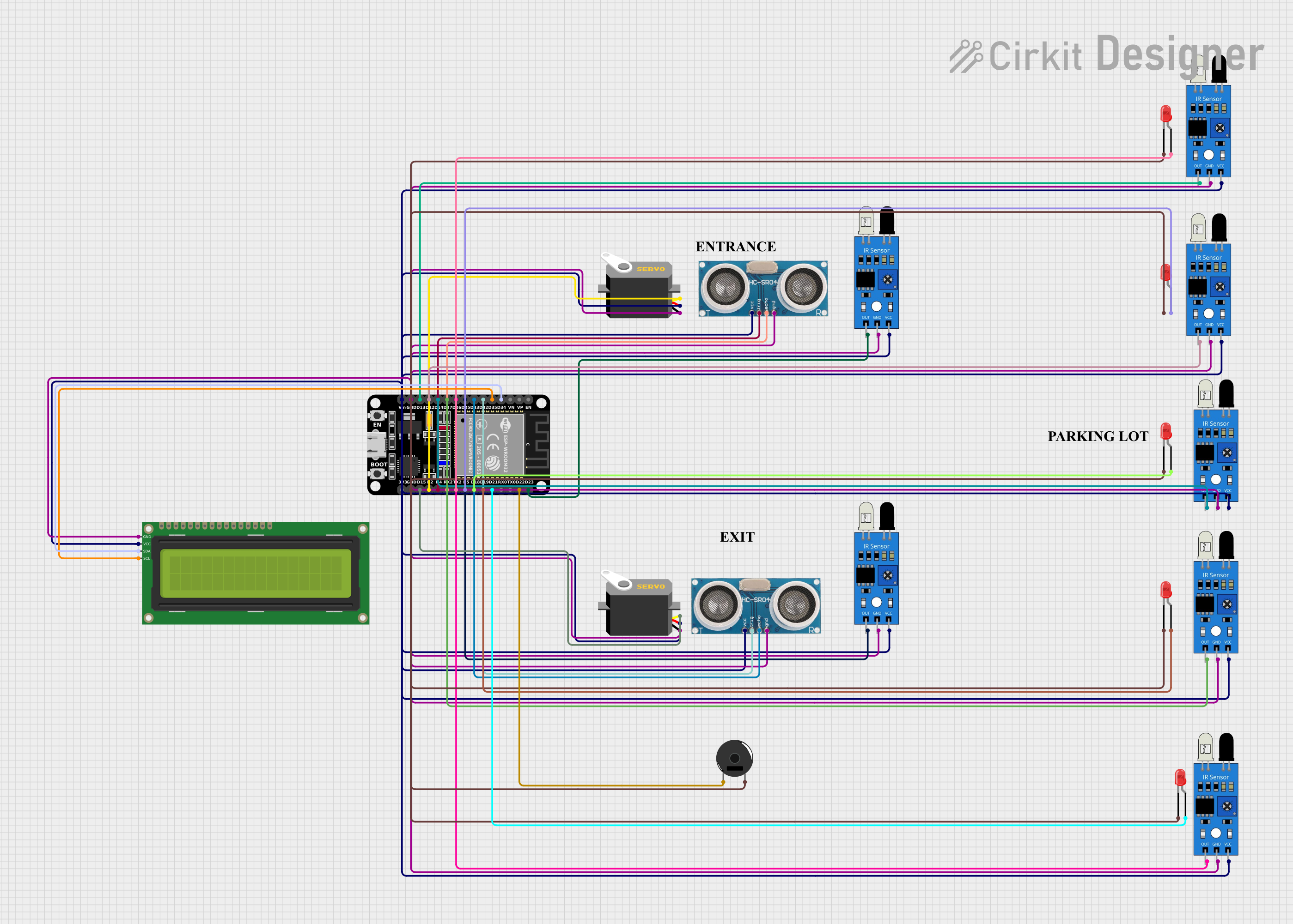
ESP32-Based Sensor Interface with Display and Actuator Control

Circuit Documentation
Summary of the Circuit
This circuit is designed to interface various sensors and actuators with an ESP32 microcontroller. The circuit includes ultrasonic sensors for distance measurement, infrared (IR) sensors for object detection, servos for actuation, LEDs for visual indication, a piezo buzzer for audio signaling, and an I2C LCD for display purposes. The ESP32 serves as the central processing unit, reading sensor inputs and controlling the actuators based on the programmed logic.
Component List
Microcontroller
- ESP32 (30 pin): A powerful microcontroller with Wi-Fi and Bluetooth capabilities, featuring a wide range of GPIO pins for interfacing with various peripherals.
Sensors
- Ultrasonic Sensor: Used for measuring distances by emitting ultrasonic waves and detecting their reflection.
- IR Sensor: Detects the presence of objects within its field of view by emitting and detecting infrared light.
Actuators
- Servo: A rotary actuator that can be precisely controlled to move to a specified angle.
Indicators
- LED (Red): Provides visual indication by emitting red light when powered.
- Piezo Buzzer: Emits a tone when powered, useful for audio signaling.
Display
- 16x2 I2C LCD: A 16-character by 2-line display that communicates with the ESP32 via the I2C protocol.
Wiring Details
ESP32 (30 pin)
- I2C Communication: Connected to the 16x2 I2C LCD for display purposes.
- SDA (Data Line) to LCD SDA
- SCL (Clock Line) to LCD SCL
- Ultrasonic Sensors: Interfaces with two ultrasonic sensors for distance measurement.
- D32 to Trigger of Ultrasonic Sensor 1
- D33 to Echo of Ultrasonic Sensor 1
- D4 to Trigger of Ultrasonic Sensor 2
- RX2 to Echo of Ultrasonic Sensor 2
- IR Sensors: Reads signals from multiple IR sensors for object detection.
- D25, D26, D27, D14, D12, D13, D23 to the output of corresponding IR sensors
- Servos: Controls two servos for actuation.
- D2 to Pulse of Servo 1
- D15 to Pulse of Servo 2
- LEDs: Powers multiple red LEDs for visual indication.
- D21, D19, D18, D5, TX2 to the anode of corresponding LEDs
- Piezo Buzzer: Generates audio signals through the piezo buzzer.
- D22 to Pin 1 of Piezo Buzzer
- Common Ground: All GND pins of the components are connected to the GND pin of the ESP32.
- Power Supply: The Vin pin of the ESP32 supplies power to all VCC/+VCC pins of the sensors, servos, and the LCD.
Ultrasonic Sensor
- VCC: Power supply (+5V)
- Trigger: Input signal to initiate distance measurement
- Echo: Output signal indicating the duration of the ultrasonic pulse travel
- GND: Ground connection
IR Sensor
- Out: Digital output signal indicating the detection of an object
- VCC: Power supply (+5V)
- GND: Ground connection
Servo
- VCC: Power supply (+5V)
- GND: Ground connection
- Pulse: PWM input signal controlling the servo position
LED (Red)
- Anode: Positive terminal connected to a GPIO pin on the ESP32
- Cathode: Negative terminal connected to the ground
Piezo Buzzer
- Pin 1: Input signal that generates the tone when powered
- Pin 2: Ground connection
16x2 I2C LCD
- VCC: Power supply (+5V)
- GND: Ground connection
- SDA: I2C data line
- SCL: I2C clock line
Documented Code
No code has been provided for the microcontroller. The documentation of the code would typically include a description of the functionality, setup, and loop routines, as well as any functions or libraries used to interface with the sensors and actuators. Since no code is available, this section cannot be completed.