
Arduino Mega 2560-Based Environmental Monitoring System with LCD Display and Bluetooth Connectivity
View and Edit Project In Cirkit Designer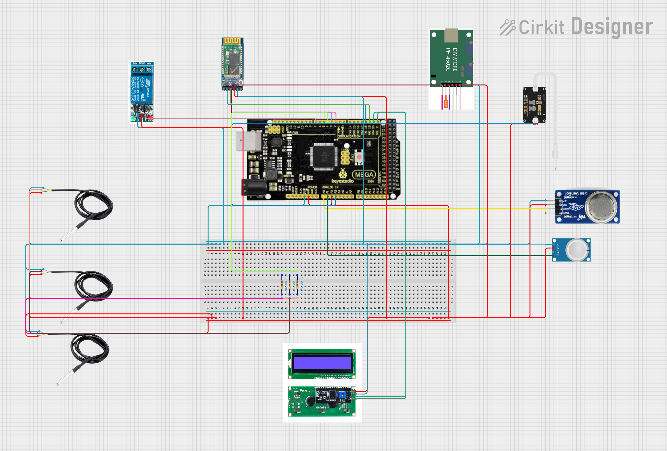
Circuit Documentation
Summary
This circuit is designed to monitor various environmental parameters including temperature, gas concentrations (methane and CO2), pH levels, and Total Dissolved Solids (TDS). The system uses an Arduino Mega 2560 R3 microcontroller to interface with multiple sensors and display the readings on an LCD. Additionally, the circuit includes a relay to control a heater based on temperature readings.
Component List
Mega 2560 R3
- Description: Microcontroller board based on the ATmega2560.
- Pins: ICSP port GND, ICSP port Reset, ICSP port MOSI, ICSP port SCK, ICSP port +VCC, ICSP port MISO, SCL, SDA, AREF, GND, D13 (PWM), D12 (PWM), D11 (PWM), D10 (PWM), D9 (PWM), D8 (PWM), D7 (PWM), D6 (PWM), D5 (PWM), D4 (PWM), D3 (PWM), D2 (PWM), D1 (TX0), D0 (RX0), D14 (TX3), D15 (RX3), D16 (TX2), D17 (RX2), D18 (TX1), D19 (RX1), D20 (SDA), D21 (SCL), + 5VCC, D22, D23, D24, D25, D26, D27, D28, D29, D30, D31, D32, D33, D34, D35, D36, D37, D38, D39, D40, D41, D42, D43, D44, D45, D46, D47, D48, D49, D50, D51, D52, D53, NC, IOREF, Reset, +3V3, +VCC IN, A0, A1, A2, A3, A4, A5, A6, A7, A8, A9, A10, A11, A12, A13, A14, A15, USB port.
DS18B20 (x3)
- Description: Digital temperature sensor.
- Pins: signal, GND, vcc.
MQ 135
- Description: Gas sensor for detecting CO2.
- Pins: D OUT, A OUT, GND, VCC.
MQ-4
- Description: Gas sensor for detecting methane.
- Pins: A0, D0, GND, VCC.
TDS Sensor
- Description: Sensor for measuring Total Dissolved Solids in water.
- Pins: AI, GND, 5V.
lcdi2c
- Description: I2C LCD display.
- Pins: GND, VCC, SDA, SCL.
HC-05
- Description: Bluetooth module.
- Pins: STATE, RXD, TXD, GND, VCC, EN.
5v relay
- Description: Relay module for switching high power devices.
- Pins: Normally Open, Common terminal, Normally Closed, In, GND, VCC.
ph4502c
- Description: pH sensor module.
- Pins: VCC, G1, G2, Po, Do, To.
Resistor (x3)
- Description: Resistor with a resistance of 1000 Ohms.
- Pins: pin1, pin2.
Wiring Details
Mega 2560 R3
- D2 (PWM): Connected to pin1 of a Resistor.
- D3 (PWM): Connected to pin1 of a Resistor.
- D4 (PWM): Connected to pin1 of a Resistor.
- D7 (PWM): Connected to In pin of 5v relay.
- D18 (TX1): Connected to RXD pin of HC-05.
- D19 (RX1): Connected to TXD pin of HC-05.
- D20 (SDA): Connected to SDA pin of lcdi2c.
- D21 (SCL): Connected to SCL pin of lcdi2c.
- A0: Connected to A OUT pin of MQ 135.
- A1: Connected to A0 pin of MQ-4.
- A2: Connected to Po pin of ph4502c.
- A3: Connected to AI pin of TDS Sensor.
- + 5VCC: Connected to vcc pins of DS18B20 sensors, VCC pin of 5v relay, VCC pin of ph4502c, VCC pin of HC-05, VCC pin of lcdi2c, 5V pin of TDS Sensor, VCC pin of MQ-4, and VCC pin of MQ 135.
- GND: Connected to GND pins of DS18B20 sensors, GND pin of 5v relay, GND pin of HC-05, GND pin of lcdi2c, GND pin of TDS Sensor, G1 pin of ph4502c, GND pin of MQ-4, and GND pin of MQ 135.
DS18B20
- signal: Connected to pin2 of a Resistor.
- GND: Connected to GND.
- vcc: Connected to + 5VCC.
MQ 135
- D OUT: Not connected.
- A OUT: Connected to A0 of Mega 2560 R3.
- GND: Connected to GND.
- VCC: Connected to + 5VCC.
MQ-4
- A0: Connected to A1 of Mega 2560 R3.
- D0: Not connected.
- GND: Connected to GND.
- VCC: Connected to + 5VCC.
TDS Sensor
- AI: Connected to A3 of Mega 2560 R3.
- GND: Connected to GND.
- 5V: Connected to + 5VCC.
lcdi2c
- GND: Connected to GND.
- VCC: Connected to + 5VCC.
- SDA: Connected to D20 (SDA) of Mega 2560 R3.
- SCL: Connected to D21 (SCL) of Mega 2560 R3.
HC-05
- STATE: Not connected.
- RXD: Connected to D18 (TX1) of Mega 2560 R3.
- TXD: Connected to D19 (RX1) of Mega 2560 R3.
- GND: Connected to GND.
- VCC: Connected to + 5VCC.
- EN: Not connected.
5v relay
- Normally Open: Not connected.
- Common terminal: Not connected.
- Normally Closed: Not connected.
- In: Connected to D7 (PWM) of Mega 2560 R3.
- GND: Connected to GND.
- VCC: Connected to + 5VCC.
ph4502c
- VCC: Connected to + 5VCC.
- G1: Connected to GND.
- G2: Not connected.
- Po: Connected to A2 of Mega 2560 R3.
- Do: Not connected.
- To: Not connected.
Resistor
- pin1: Connected to D2 (PWM), D3 (PWM), and D4 (PWM) of Mega 2560 R3.
- pin2: Connected to signal pins of DS18B20 sensors.
Code Documentation
#include <LiquidCrystal_I2C.h>
#include <Wire.h>
#include <OneWire.h>
#include <DallasTemperature.h>

#define ONE_WIRE_BUS_1 2  // Temp Sensor 1 connected to pin 2
#define ONE_WIRE_BUS_2 3  // Temp Sensor 2 connected to pin 3
#define ONE_WIRE_BUS_3 4  // Temp Sensor 3 connected to pin 4

OneWire oneWire1(ONE_WIRE_BUS_1);
OneWire oneWire2(ONE_WIRE_BUS_2);
OneWire oneWire3(ONE_WIRE_BUS_3);

DallasTemperature sensors1(&oneWire1);
DallasTemperature sensors2(&oneWire2);
DallasTemperature sensors3(&oneWire3);

LiquidCrystal_I2C lcd(0x27, 16, 2);

const float R_L = 10;
const float V_supply = 5.0;
float Ro_MQ135 = 10.0;
float Ro_MQ4 = 10.0;

const int analogInPin = A3;
int sensorValue = 0;
unsigned long int avgValue;
float b;
int buf[10], temp = 0;

#define TdsSensorPin A2
int ADC_value;
unsigned long int avgval_ADC;
int buffer_tds[10], temp1;
float baselineTDS = 100;  // Example baseline value when the sensor is not