Cirkit Designer
Your all-in-one circuit design IDE
Home /
Project Documentation
Arduino-Controlled Load Cell Measurement System with Servo Feedback
Circuit Documentation
Summary
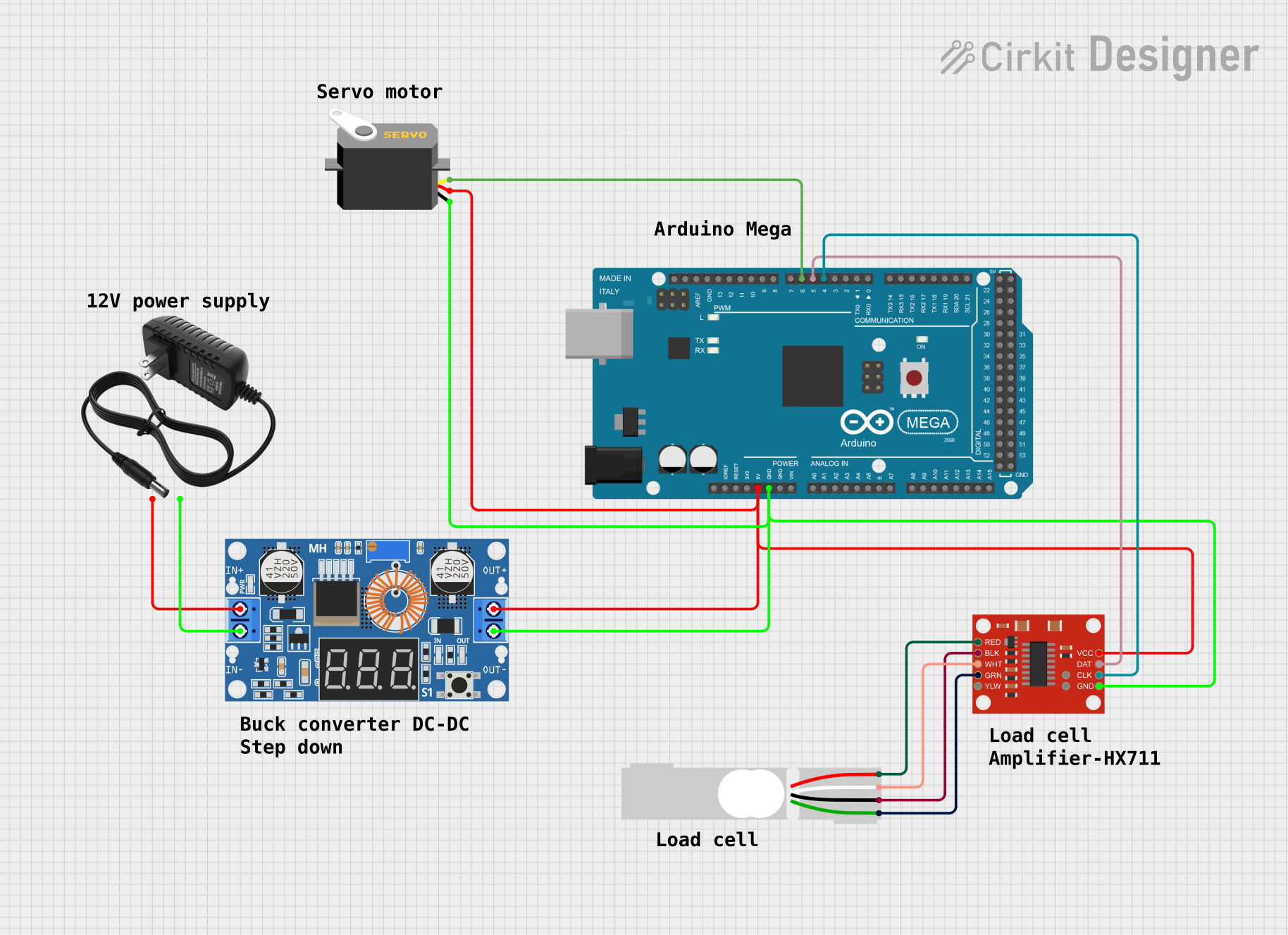
This circuit is designed to interface a load cell with an Arduino Mega 2560 microcontroller through a SparkFun Load Cell Amplifier (HX711). The load cell measures mechanical force and the HX711 amplifies the signal for the microcontroller to process. A servo motor is also included, which can be controlled by the Arduino based on the load cell's readings. Power is supplied by a 12V power supply, which is stepped down to a lower voltage suitable for the components using an XL4015 5A DC Buck Step-down converter.
Component List
Load Cell - Red/white/black/green
- A sensor that converts a force into an electrical signal.
- Pins: E+, A-, E-, A+
12V Power Supply
- Provides the main power source for the circuit.
- Pins: +, -
XL4015 5A DC Buck Step-down
- A voltage regulator that steps down the voltage from the power supply to a level suitable for the other components.
- Pins: Output +, Output -, Input +, Input -
SparkFun Load Cell Amplifier - HX711
- Amplifies the signal from the load cell for the Arduino to read.
- Pins: GND, CLK, DAT, VCC, YLW, GRN, WHT, BLK, RED, B-, B+
Arduino Mega 2560
- The main microcontroller unit that processes the input from the HX711 and controls the servo motor.
- Pins: Various digital and analog I/O, power, and ground pins.
Servo
- An actuator that can be positioned with PWM signals from the Arduino.
- Pins: gnd, vcc, pulse
Wiring Details
Load Cell - Red/white/black/green
- E+ connected to HX711 RED
- A- connected to HX711 WHT
- E- connected to HX711 BLK
- A+ connected to HX711 GRN
12V Power Supply
- connected to XL4015 Input +
- connected to XL4015 Input -
XL4015 5A DC Buck Step-down
- Input + connected to 12V Power Supply +
- Input - connected to 12V Power Supply -
- Output + connected to Servo vcc, HX711 VCC, and Arduino 5V
- Output - connected to Servo gnd, HX711 GND, and Arduino GND
SparkFun Load Cell Amplifier - HX711
- RED connected to Load Cell E+
- WHT connected to Load Cell A-
- BLK connected to Load Cell E-
- GRN connected to Load Cell A+
- VCC connected to XL4015 Output +
- GND connected to XL4015 Output -
- CLK connected to Arduino D4 PWM
- DAT connected to Arduino D5 PWM
Arduino Mega 2560
- 5V connected to XL4015 Output +
- GND connected to XL4015 Output -
- D4 PWM connected to HX711 CLK
- D5 PWM connected to HX711 DAT
- D6 PWM connected to Servo pulse
Servo
- gnd connected to XL4015 Output -
- vcc connected to XL4015 Output +
- pulse connected to Arduino D6 PWM
Documented Code
Arduino Mega 2560 - sketch.ino
void setup() {
  // put your setup code here, to run once:

}

void loop() {
  // put your main code here, to run repeatedly:

}
Arduino Mega 2560 - documentation.txt
(No additional documentation provided)