
Arduino Nano Light Sensor with OLED Display and LED Indicator
View and Edit Project In Cirkit Designer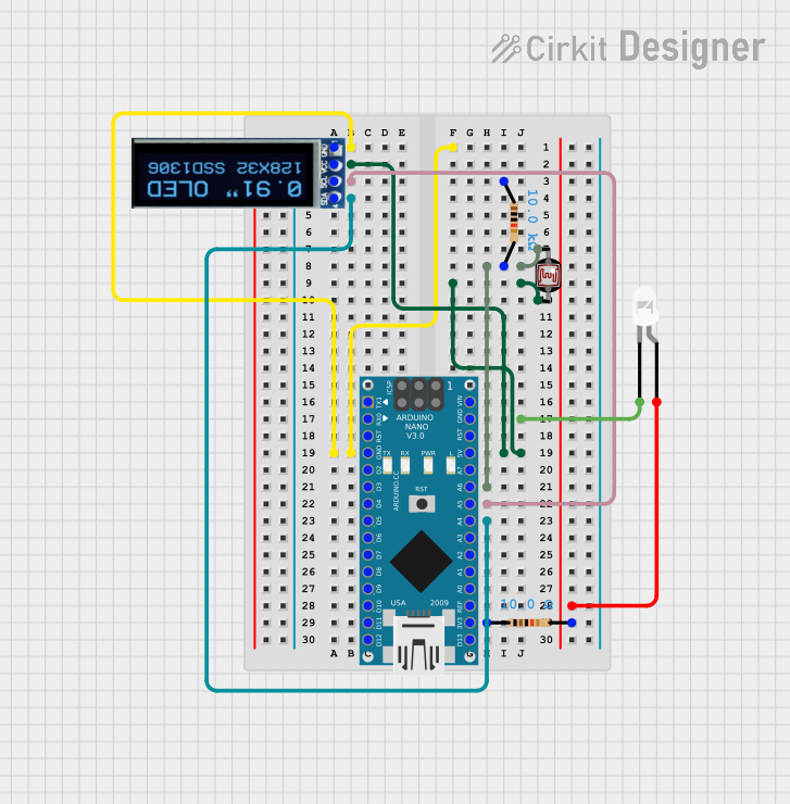
Circuit Documentation
Summary
This document provides a detailed overview of a circuit that includes an Arduino Nano, resistors, a photocell (LDR), an OLED display, and an LED. The circuit is designed to interface these components and includes the necessary wiring and embedded code for the Arduino Nano.
Component List
Arduino Nano
- Description: A small, complete, and breadboard-friendly board based on the ATmega328P.
- Pins: D1/TX, D0/RX, RESET, GND, D2, D3, D4, D5, D6, D7, D8, D9, D10, D11/MOSI, D12/MISO, VIN, 5V, A7, A6, A5, A4, A3, A2, A1, A0, AREF, 3V3, D13/SCK
Resistor (10k Ohms)
- Description: A resistor with a resistance of 10k Ohms.
- Pins: pin1, pin2
- Properties:
- Resistance: 10k Ohms
Photocell (LDR)
- Description: A light-dependent resistor that changes its resistance based on the light intensity.
- Pins: pin 0, pin 1
OLED Display (128x32)
- Description: A 128x32 pixel OLED display.
- Pins: SDA, SCL, VCC, GND
Resistor (10 Ohms)
- Description: A resistor with a resistance of 10 Ohms.
- Pins: pin1, pin2
- Properties:
- Resistance: 10 Ohms
LED (White)
- Description: A two-pin white LED.
- Pins: cathode, anode
Wiring Details
Arduino Nano
- GND is connected to:
- GND of the OLED Display
- Cathode of the LED
- 5V is connected to:
- VCC of the OLED Display
- pin 1 of the Photocell (LDR)
- A5 is connected to:
- SCL of the OLED Display
- A4 is connected to:
- SDA of the OLED Display
- A6 is connected to:
- pin 2 of the 10k Ohm Resistor
- 3V3 is connected to:
- pin 1 of the 10 Ohm Resistor
Resistor (10k Ohms)
- pin1 is connected to:
- pin 0 of the Photocell (LDR)
- pin2 is connected to:
- A6 of the Arduino Nano
Photocell (LDR)
- pin 0 is connected to:
- pin 1 of the 10k Ohm Resistor
- pin 1 is connected to:
- 5V of the Arduino Nano
OLED Display (128x32)
- GND is connected to:
- GND of the Arduino Nano
- VCC is connected to:
- 5V of the Arduino Nano
- pin 1 of the Photocell (LDR)
- SCL is connected to:
- A5 of the Arduino Nano
- SDA is connected to:
- A4 of the Arduino Nano
Resistor (10 Ohms)
- pin1 is connected to:
- 3V3 of the Arduino Nano
- pin2 is connected to:
- Anode of the LED
LED (White)
- cathode is connected to:
- GND of the Arduino Nano
- anode is connected to:
- pin 2 of the 10 Ohm Resistor
Code Documentation
Arduino Nano Code
void setup() {
  // put your setup code here, to run once:

}

void loop() {
  // put your main code here, to run repeatedly:

}
This code is a basic template for the Arduino Nano. The setup() function is where you initialize your components and settings, and the loop() function is where the main code runs repeatedly.
This concludes the documentation for the circuit.