
Arduino-Controlled Sequential LED Display with 74HC595 Shift Register
View and Edit Project In Cirkit Designer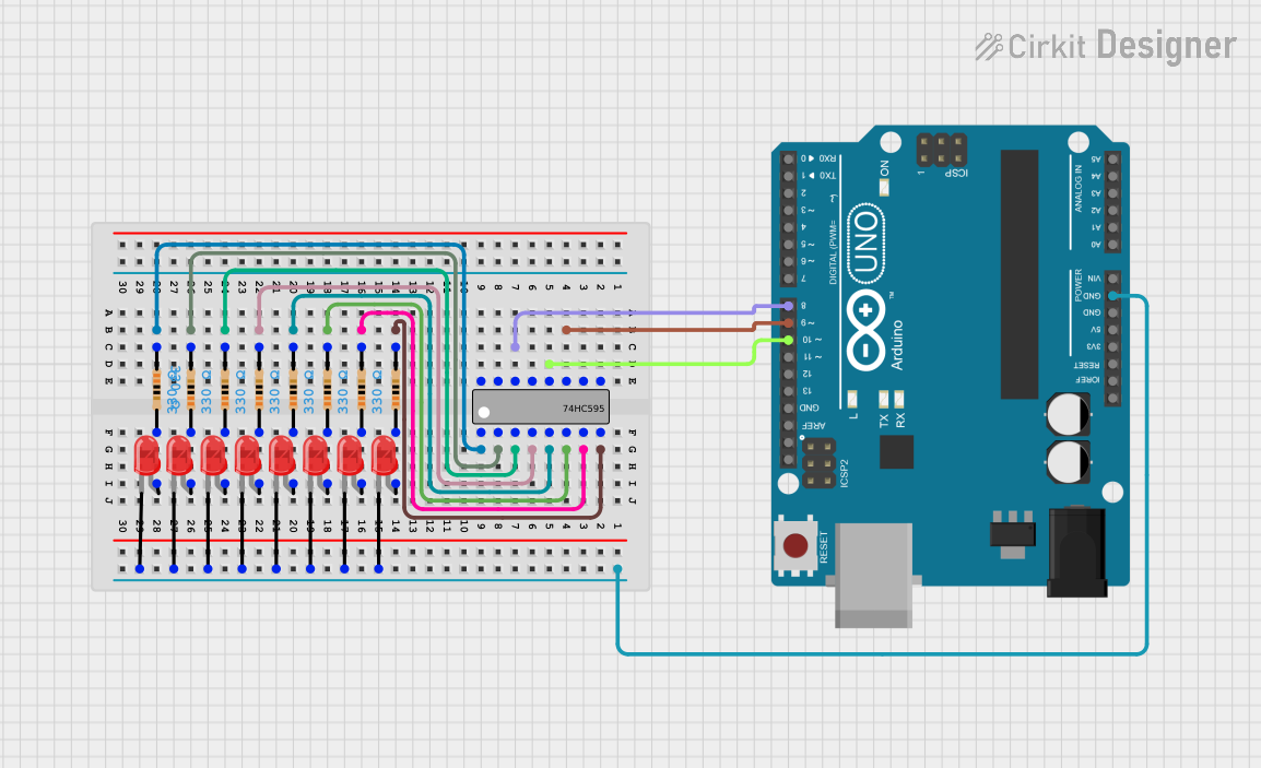
Circuit Documentation
Summary
This circuit is designed to control a series of 8 red LEDs using an Arduino UNO microcontroller and a 74HC595 shift register. The LEDs are arranged to light up sequentially, creating a visual effect. The Arduino UNO is programmed to send serial data to the 74HC595, which then sets the state of each LED. Each LED is connected to the shift register through a current-limiting resistor to protect the LEDs from excessive current.
Component List
Arduino UNO
- Description: A microcontroller board based on the ATmega328P.
- Pins: UNUSED, IOREF, Reset, 3.3V, 5V, GND, Vin, A0-A5, SCL, SDA, AREF, D0-D13
74HC595 Shift Register
- Description: An 8-bit serial-in, parallel-out shift register.
- Pins: Q0-Q7, GND, VCC, DS (DATA), OE (Enable), ST_CP (RCLK), SH_CP (SRCLK), MR (SRCLR), Q7' (QH)
LED: Two Pin (red)
- Description: A standard red LED with two pins, anode, and cathode.
- Pins: cathode, anode
Resistor
- Description: A passive two-terminal electrical component that implements electrical resistance as a circuit element.
- Resistance: 330 Ohms
Wiring Details
Arduino UNO
- GND: Connected to the cathodes of all LEDs through their respective resistors.
- D8: Connected to the DS (DATA) pin of the 74HC595.
- D9: Connected to the SH_CP (SRCLK) pin of the 74HC595.
- D10: Connected to the ST_CP (RCLK) pin of the 74HC595.
74HC595 Shift Register
- Q0-Q7: Each connected to the anode of a respective LED through a 330 Ohm resistor.
- GND: Connected to the GND pin of the Arduino UNO.
- VCC: Should be connected to a positive voltage supply (not specified in the net list).
- DS (DATA), ST_CP (RCLK), SH_CP (SRCLK): Connected to the Arduino UNO as specified above.
LEDs
- Anode: Each connected to a respective Q0-Q7 output of the 74HC595 through a 330 Ohm resistor.
- Cathode: All connected together and then to the GND pin of the Arduino UNO.
Resistors
- One side (pin2): Each connected to a respective Q0-Q7 output of the 74HC595.
- Other side (pin1): Each connected to the anode of a respective LED.
Documented Code
/*
 * This Arduino sketch controls 8 red LEDs connected through a 74HC595 shift
 * register. The LEDs will turn on sequentially one by one in a loop.
 */

// Pin definitions
const int dataPin = 8;   // DS (DATA) pin of 74HC595
const int latchPin = 10; // ST_CP (RCLK) pin of 74HC595
const int clockPin = 9;  // SH_CP (SRCLK) pin of 74HC595

void setup() {
  // Set pin modes
  pinMode(dataPin, OUTPUT);
  pinMode(latchPin, OUTPUT);
  pinMode(clockPin, OUTPUT);
}

void loop() {
  for (int i = 0; i < 8; i++) {
    // Create a byte with only the i-th bit set
    byte ledState = 1 << i;
    // Update the shift register
    updateShiftRegister(ledState);
    // Wait for a while
    delay(500);
  }
}

void updateShiftRegister(byte data) {
  // Set latchPin low to start sending data
  digitalWrite(latchPin, LOW);
  // Shift out the data
  shiftOut(dataPin, clockPin, MSBFIRST, data);
  // Set latchPin high to lock the data
  digitalWrite(latchPin, HIGH);
}
This code is designed to run on the Arduino UNO microcontroller. It initializes three pins as outputs to interface with the 74HC595 shift register. In the main loop, it sequentially lights up each LED by shifting a bit through the register, pausing for half a second between each LED. The updateShiftRegister function handles the low-level details of setting the shift register's pins to update the LED states.