Raspberry Pi-Based Pulse Oximeter with LED Indicators
Circuit Documentation
Summary
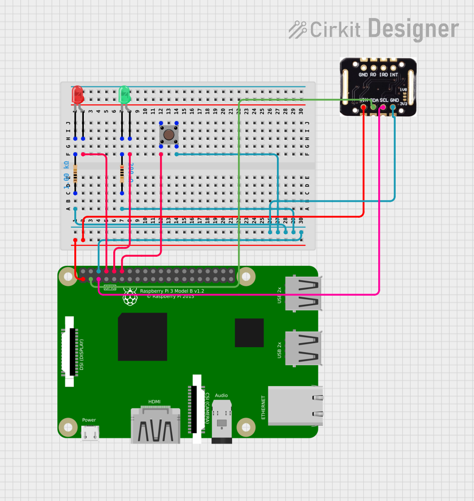
The circuit in question appears to be designed for interfacing a Raspberry Pi 3B with a MAX30102 sensor and two LEDs (one green and one red). The MAX30102 is likely used for sensing purposes, possibly for measuring heart rate or blood oxygen levels, as it is commonly used in health monitoring devices. The Raspberry Pi 3B serves as the central processing unit, controlling the LEDs and communicating with the MAX30102 sensor via I2C protocol. The circuit also includes a pushbutton and resistors, which may be used for user input and current limiting, respectively.
Component List
MAX30102
- Description: A high-sensitivity pulse oximeter and heart-rate sensor for wearable health.
- Pins: VIN, SDA, SCL, GND
LED: Two Pin (green)
- Description: A green LED for indication purposes.
- Pins: cathode, anode
LED: Two Pin (red)
- Description: A red LED for indication purposes.
- Pins: cathode, anode
Resistor (1 kOhm)
- Description: A resistor with a resistance of 1000 Ohms, likely used for current limiting.
- Pins: pin1, pin2
Resistor (200 Ohms)
- Description: A resistor with a resistance of 200 Ohms, likely used for current limiting.
- Pins: pin1, pin2
Pushbutton
- Description: A standard pushbutton for user input.
- Pins: Pin 3 (out), Pin 4 (out), Pin 1 (in), Pin 2 (in)
Raspberry Pi 3B
- Description: A small single-board computer with GPIO capabilities.
- Pins: 3v3, GPIO2, GPIO3, GPIO4, GND, GPIO17, GPIO27, GPIO22, 3V3, GPIO10, GPIO9, GPIO11, ID_SD, GPIO5, GPIO6, GPIO13, GPIO19, GPIO26, GPIO21, GPIO20, GPIO16, GPIO12, ID_SC, GPIO7, GPIO8, GPIO25, GPIO24, GPIO23, GPIO18, GPIO15, GPIO14, 5V
Wiring Details
MAX30102
- VIN: Connected to Raspberry Pi 3B 3v3
- SDA: Connected to Raspberry Pi 3B GPIO2
- SCL: Connected to Raspberry Pi 3B GPIO3
- GND: Shared ground with Raspberry Pi 3B and Pushbutton
LED: Two Pin (green)
- Anode: Connected to Raspberry Pi 3B GPIO15
- Cathode: Connected to Resistor (200 Ohms) pin1
LED: Two Pin (red)
- Anode: Connected to Raspberry Pi 3B GPIO14
- Cathode: Connected to Resistor (1 kOhm) pin2
Resistor (1 kOhm)
- Pin1: Connected to Resistor (200 Ohms) pin2
- Pin2: Connected to LED: Two Pin (red) cathode
Resistor (200 Ohms)
- Pin1: Connected to LED: Two Pin (green) cathode
- Pin2: Connected to Resistor (1 kOhm) pin1
Pushbutton
- Pin 3 (out): Shared ground with MAX30102 and Raspberry Pi 3B
- Pin 4 (out): Shared ground with MAX30102 and Raspberry Pi 3B
- Pin 1 (in): Connected to Raspberry Pi 3B GPIO18
- Pin 2 (in): Connected to Raspberry Pi 3B GPIO18
Raspberry Pi 3B
- 3v3: Powers MAX30102 VIN
- GPIO2: I2C SDA for MAX30102
- GPIO3: I2C SCL for MAX30102
- GND: Shared ground with MAX30102 and Pushbutton
- GPIO14: Controls LED: Two Pin (red) anode
- GPIO15: Controls LED: Two Pin (green) anode
- GPIO18: Receives input from Pushbutton
Documented Code
No code was provided for the microcontrollers in the circuit. Typically, the code would be used to control the behavior of the LEDs, read sensor data from the MAX30102, and process the pushbutton input. Without the code, we cannot document the specific functionalities implemented in the firmware.