Cirkit Designer
Your all-in-one circuit design IDE
Home /
Project Documentation
Arduino 101-Based Fingerprint Access Control System with Buzzer and Servo
Circuit Documentation
Summary
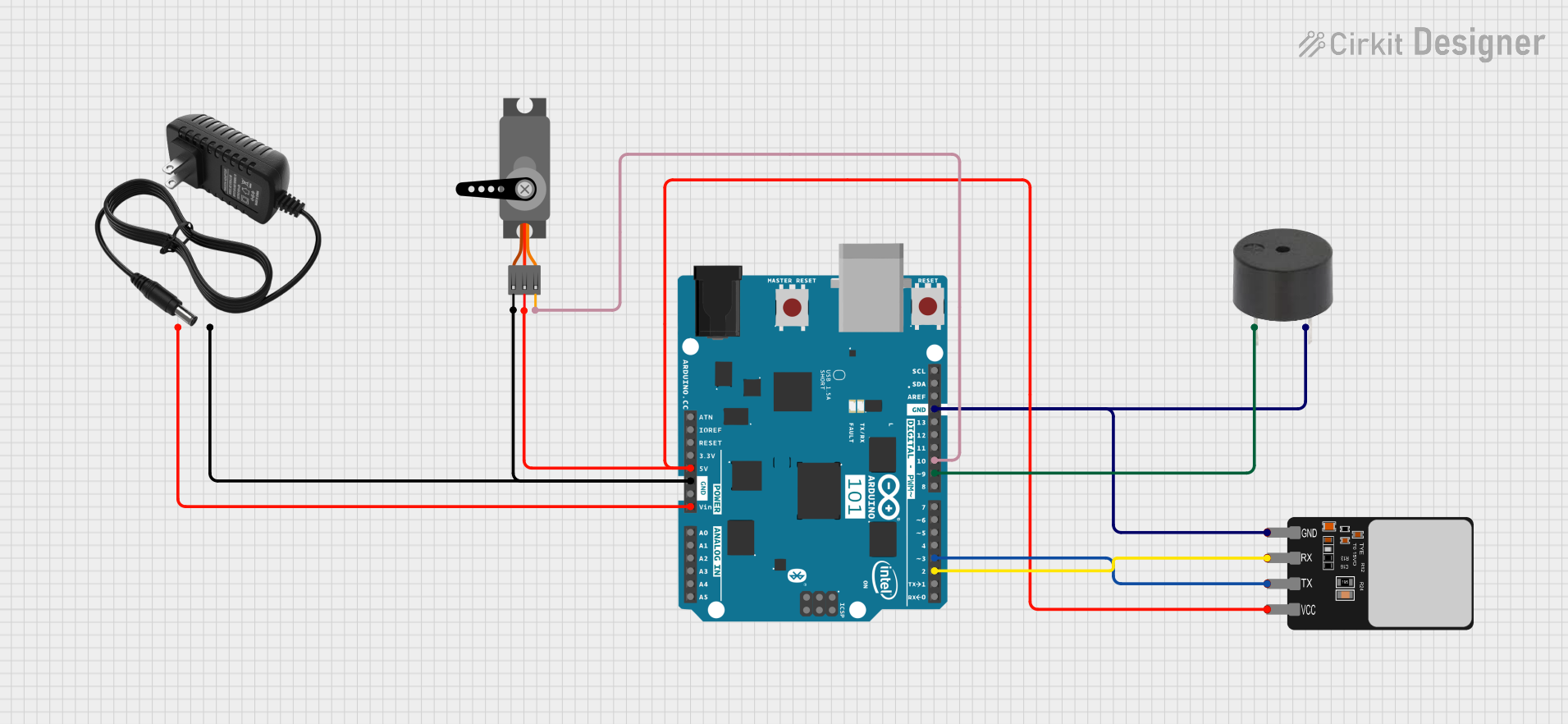
This document provides a detailed overview of a circuit that includes a Fingerprint Scanner, a Buzzer, a 12V Power Supply, an Arduino 101, and a Servo. The circuit is designed to interface these components for a specific application, with the Arduino 101 serving as the central microcontroller.
Component List
Fingerprint Scanner
- Description: A biometric sensor used to capture and verify fingerprints.
- Pins: VCC, TX, RX, GND
Buzzer
- Description: An audio signaling device that emits sound when activated.
- Pins: PIN, GND
12V Power Supply
- Description: Provides a 12V power source for the circuit.
- Pins: +, -
Arduino 101
- Description: A microcontroller board based on the Intel Curie module, used to control and interface with other components.
- Pins: A5/SCL, A4/SDA, AREF, GND, D13/SCK, D12/MISO, D11 PWM/MOSI, D10 PWM/SS, D9 PWM, D8, D7, D6 PWM, D5 PWM, D4, D3 PWM, D2, D1/TX, D0/RX, AIN, ioref, RESET, 3V3, 5V, VIN, A0, A1, A2, A3, ICSP MISO, ICSP SCK, ICSP MOSI
Servo
- Description: A motor that can be precisely controlled to move to a specific position.
- Pins: GND, VCC, PWM
Wiring Details
Fingerprint Scanner
- VCC connected to 5V on Arduino 101
- TX connected to D3 PWM on Arduino 101
- RX connected to D2 on Arduino 101
- GND connected to GND on Arduino 101 and Buzzer
Buzzer
- PIN connected to D9 PWM on Arduino 101
- GND connected to GND on Arduino 101 and Fingerprint Scanner
12V Power Supply
- + connected to VIN on Arduino 101
- - connected to GND on Arduino 101 and Servo
Arduino 101
- 5V connected to VCC on Fingerprint Scanner and Servo
- D3 PWM connected to TX on Fingerprint Scanner
- D2 connected to RX on Fingerprint Scanner
- GND connected to GND on Fingerprint Scanner, Buzzer, and Servo
- D9 PWM connected to PIN on Buzzer
- VIN connected to + on 12V Power Supply
- D10 PWM/SS connected to PWM on Servo
Servo
- VCC connected to 5V on Arduino 101
- GND connected to GND on Arduino 101 and 12V Power Supply
- PWM connected to D10 PWM/SS on Arduino 101
Code
No code provided for this circuit.
This document provides a comprehensive overview of the circuit, including a summary, detailed component list, wiring details, and code documentation. This should serve as a useful reference for understanding and replicating the circuit.