
Arduino-Based Automatic Cooker with Temperature Control and Servo-Operated Ingredient Dispensers
View and Edit Project In Cirkit Designer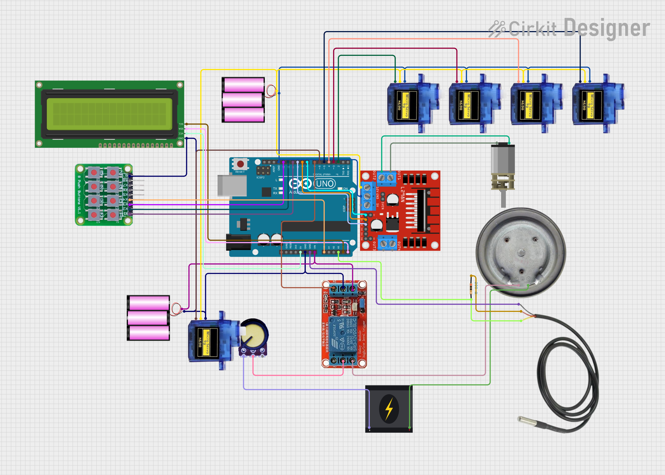
Automatic Cooker Circuit Documentation
Summary
This document provides a detailed overview of the Automatic Cooker circuit. The circuit includes various components such as a temperature sensor, heater element, multiple servo motors, a DC motor, a relay, an LCD display, and an Arduino UNO microcontroller. The circuit is designed to automate the cooking process by controlling the heating, stirring, and dispensing of ingredients.
Component List
Temperature Sensor
- Description: Measures the temperature of the cooking environment.
- Pins: Temp GND Black, Temp VDD Red, Temp DQ Data Yellow
Heater Element
- Description: Provides heat to the cooking environment.
- Pins: VCC, GND
Micro Servo 9G
- Description: Controls the opening of ingredient containers.
- Pins: GND, +5V, PWM
Potentiometer
- Description: Used to adjust the heating element.
- Pins: GND, Output, VCC
DC Mini Metal Gear Motor
- Description: Stirs the ingredients.
- Pins: IN1, IN2
240v Power Source
- Description: Provides power to the heater element.
- Pins: Live, Neutral
Battery 12v
- Description: Provides power to the circuit.
- Pins: +, -
12v Relay
- Description: Controls the heater element.
- Pins: NO, COM, NC, IN, DC-, DC+
L298N DC Motor Driver
- Description: Drives the DC motor.
- Pins: OUT1, OUT2, 12V, GND, 5V, OUT3, OUT4, 5V-ENA-JMP-I, 5V-ENA-JMP-O, +5V-J1, +5V-J2, ENA, IN1, IN2, IN3, IN4, ENB
Resistor
- Description: Used in the temperature sensor circuit.
- Pins: pin1, pin2
- Properties: Resistance: 200 Ohms
16x2 I2C LCD
- Description: Displays information.
- Pins: GND, VCC, SDA, SCL
8 Push Button Board PCB
- Description: Provides user input.
- Pins: K1, K2, K3, K4, K5, K6, K7, K8, GROUND
Arduino UNO
- Description: Microcontroller that controls the entire circuit.
- Pins: UNUSED, IOREF, Reset, 3.3V, 5V, GND, Vin, A0, A1, A2, A3, A4, A5, SCL, SDA, AREF, D13, D12, D11, D10, D9, D8, D7, D6, D5, D4, D3, D2, D1, D0
Wiring Details
Temperature Sensor
- Temp GND Black connected to Arduino UNO GND
- Temp VDD Red connected to Resistor pin1
- Temp DQ Data Yellow connected to Resistor pin2 and Arduino UNO A3
Heater Element
- VCC connected to 240v Power Source Live
- GND connected to 12v Relay NC
Micro Servo 9G
- GND connected to Arduino UNO GND
- +5V connected to L298N DC Motor Driver 12V
- PWM connected to:
- Servo 1: Arduino UNO D2
- Servo 2: Arduino UNO D3
- Servo 3: Arduino UNO D4
- Servo 4: Arduino UNO D5
Potentiometer
- GND connected to 240v Power Source Neutral
- Output connected to 12v Relay COM
- VCC connected to Arduino UNO 5V
DC Mini Metal Gear Motor
- IN1 connected to L298N DC Motor Driver OUT2
- IN2 connected to L298N DC Motor Driver OUT1
240v Power Source
- Live connected to Heater Element VCC
- Neutral connected to Potentiometer GND
Battery 12v
- + connected to Arduino UNO Vin and 12v Relay DC+
- - connected to Arduino UNO GND and 12v Relay DC-
12v Relay
- NO connected to Heater Element GND
- COM connected to Potentiometer Output
- NC connected to Heater Element GND
- IN connected to Arduino UNO D7
- DC- connected to Battery 12v -
- DC+ connected to Battery 12v +
L298N DC Motor Driver
- GND connected to Arduino UNO GND
- 12V connected to Battery 12v +
- IN1 connected to Arduino UNO D9
- IN2 connected to Arduino UNO D10
- ENA connected to Arduino UNO D8
- OUT1 connected to DC Mini Metal Gear Motor IN2
- OUT2 connected to DC Mini Metal Gear Motor IN1
Resistor
- pin1 connected to Temperature Sensor Temp VDD Red
- pin2 connected to Temperature Sensor Temp DQ Data Yellow and Arduino UNO A3
16x2 I2C LCD
- GND connected to Arduino UNO GND
- VCC connected to Arduino UNO 5V
- SDA connected to Arduino UNO A5
- SCL connected to Arduino UNO A4
8 Push Button Board PCB
- GROUND connected to Arduino UNO GND
- K1 connected to Arduino UNO D11
- K2 connected to Arduino UNO D12
- K3 connected to Arduino UNO D13
- K4 connected to Arduino UNO A0
Arduino UNO
- GND connected to:
- Temperature Sensor Temp GND Black
- Micro Servo 9G GND
- 16x2 I2C LCD GND
- 12v Relay DC-
- Battery 12v -
- 8 Push Button Board PCB GROUND
- 5V connected to:
- 16x2 I2C LCD VCC
- Potentiometer VCC
- Vin connected to Battery 12v +
- A0 connected to 8 Push Button Board PCB K4
- A3 connected to Temperature Sensor Temp DQ Data Yellow and Resistor pin2
- A4 connected to 16x2 I2C LCD SCL
- A5 connected to 16x2 I2C LCD SDA
- D2 connected to Micro Servo 9G PWM
- D3 connected to Micro Servo 9G PWM
- D4 connected to Micro Servo 9G PWM
- D5 connected to Micro Servo 9G PWM
- D6 connected to Micro Servo 9G PWM
- D7 connected to 12v Relay IN
- D8 connected to L298N DC Motor Driver ENA
- D9 connected to L298N DC Motor Driver IN1
- D10 connected to L298N DC Motor Driver IN2
- D11 connected to 8 Push Button Board PCB K1
- D12 connected to 8 Push Button Board PCB K2
- D13 connected to 8 Push Button Board PCB K3
Code Documentation
/*
 * Automatic Cooker
 * This code controls an automatic cooker with the following features:
 * - Four servo motors to open ingredient containers
 * - A DC motor to stir the ingredients
 * - A heater element controlled by a relay and potentiometer
 * - A temperature sensor to monitor and control the heating process
 * - The cooking process lasts 15 minutes with specific timings for each step
 */

#include <Servo.h>

// Pin definitions
const int servoPins[4] = {2, 3, 4, 5};
const int relayPin = 7;
const int tempSensorPin = A0;
const int motorEnablePin = 8;
const int motorIn1Pin = 9;
const int motorIn2Pin = 10;

// Servo objects
Servo servos[4];

// Timing variables
unsigned long startTime;

void setup() {
  // Initialize serial communication
  Serial.begin(9600);

  // Initialize servos
  for (int i = 0; i < 4; i++) {
    servos[i].attach(servoPins[i]);