
ESP32-Based BLE Joystick with Potentiometer Control and LED Indicator
View and Edit Project In Cirkit Designer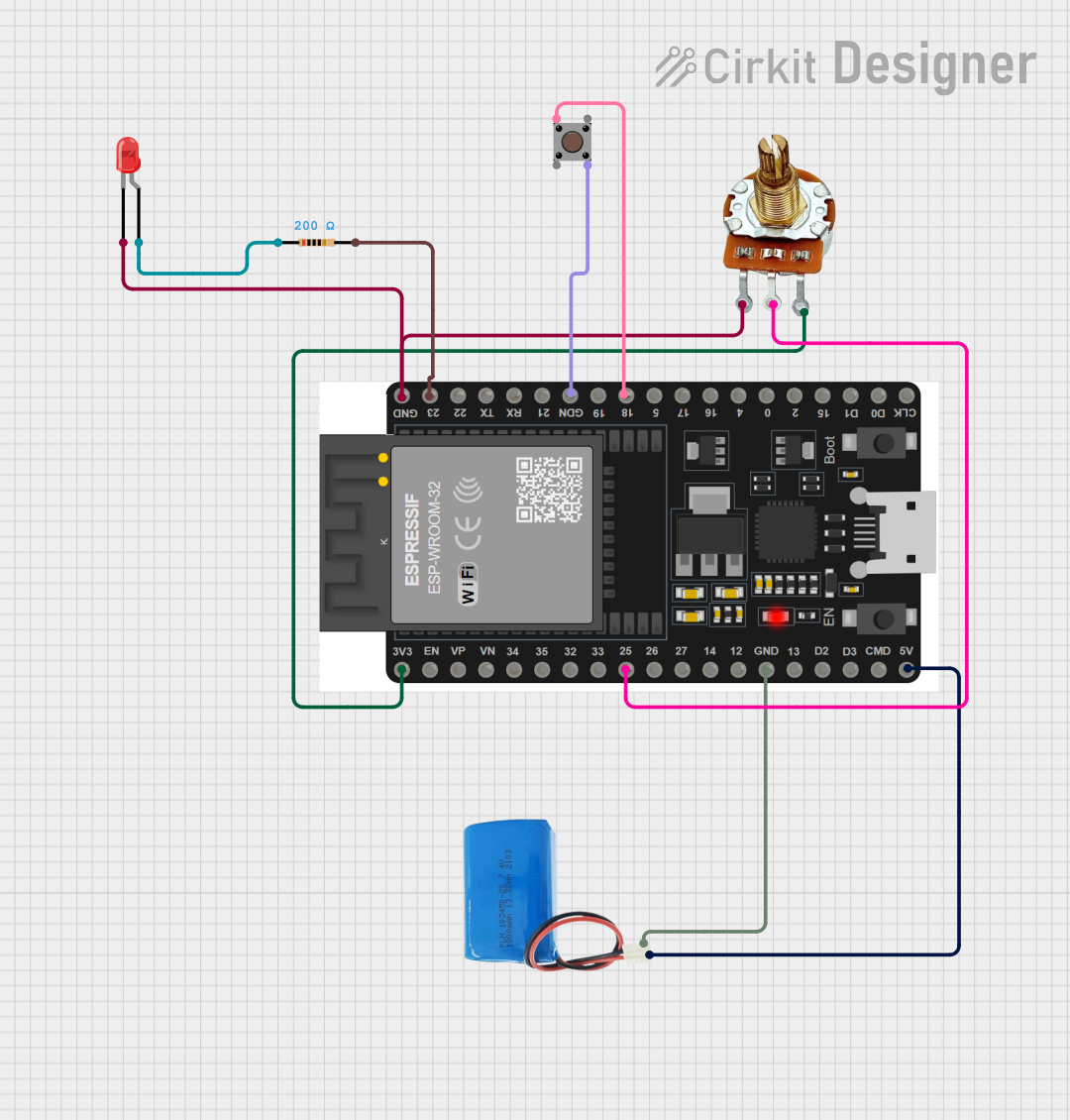
Circuit Documentation
Summary
This circuit is designed to interface an ESP32 microcontroller with a rotary potentiometer, a pushbutton, an LED, and a resistor. The ESP32 is powered by a 5V battery and communicates via Bluetooth to act as a joystick. The potentiometer is used to control the joystick's X-axis, while the pushbutton can be used for additional input. The LED is connected through a resistor to indicate the status of the circuit.
Component List
5V Battery
- Description: Power source for the circuit.
- Pins: Positive, Negative
ESP32 38 PINS
- Description: Microcontroller with Bluetooth capabilities.
- Pins: GND, 23, 22/SCL, 1, 2, 21/SDA, 19, 18, 5, 17/TX2, 16/RX2, 4, 0, 15, D1, D0, CLK, 3V3, EN, VP, VN, 34, 35, 32, 33, 25, 26, 27, 14, 12, 13, D2, D3, 11, 5V/VIN
PR-Rotary Potentiometer
- Description: Variable resistor used to control the joystick's X-axis.
- Pins: GND, OUT, VCC
LED: Two Pin (red)
- Description: Indicator LED.
- Pins: Cathode, Anode
Resistor
- Description: Limits current to the LED.
- Pins: Pin1, Pin2
- Properties:
- Resistance: 200 Ohms
Pushbutton
- Description: User input button.
- Pins: Pin 3 (out), Pin 4 (out), Pin 1 (in), Pin 2 (in)
Wiring Details
5V Battery
- Positive connected to ESP32 38 PINS pin 5V/VIN
- Negative connected to ESP32 38 PINS pin GND
ESP32 38 PINS
- GND connected to:
- 5V Battery pin Negative
- PR-Rotary Potentiometer pin GND
- LED: Two Pin (red) pin Cathode
- Pushbutton pin Pin 4 (out)
- 5V/VIN connected to 5V Battery pin Positive
- 23 connected to Resistor pin Pin2
- 18 connected to Pushbutton pin Pin 1 (in)
- 3V3 connected to PR-Rotary Potentiometer pin VCC
- 25 connected to PR-Rotary Potentiometer pin OUT
PR-Rotary Potentiometer
- GND connected to ESP32 38 PINS pin GND
- OUT connected to ESP32 38 PINS pin 25
- VCC connected to ESP32 38 PINS pin 3V3
LED: Two Pin (red)
- Cathode connected to ESP32 38 PINS pin GND
- Anode connected to Resistor pin Pin1
Resistor
- Pin1 connected to LED: Two Pin (red) pin Anode
- Pin2 connected to ESP32 38 PINS pin 23
Pushbutton
- Pin 4 (out) connected to ESP32 38 PINS pin GND
- Pin 1 (in) connected to ESP32 38 PINS pin 18
Code Documentation
Code for ESP32 Microcontroller
#include <BleGamepad.h>

BleGamepad bleGamepad("ESP32 Joystick", "ESP32 Dev Kit", 100); // Device name and information

const int potPin = 25; // ADC pin for potentiometer

void setup() {
  Serial.begin(9600);
  Serial.println("Starting BLE Joystick...");

  // Initialize BLE joystick
  bleGamepad.begin();
}

void loop() {
  if (bleGamepad.isConnected()) {
    // Read potentiometer value
    int rawValue = analogRead(potPin);

    // Map value to joystick range (-32767 to 32767)
    int joystickValue = map(rawValue, 0, 4095, -32767, 32767);

    // Send X-axis value
    bleGamepad.setAxes(joystickValue, 0, 0, 0, 0, 0); // Set X-axis, other axes 0

    // Small delay for transmission stability
    delay(10);
  }
}
Code File Information
- File Name: sketch.ino
- Description: This code initializes the ESP32 as a Bluetooth joystick. It reads the value from the rotary potentiometer and maps it to the X-axis of the joystick. The joystick value is then sent via Bluetooth.