
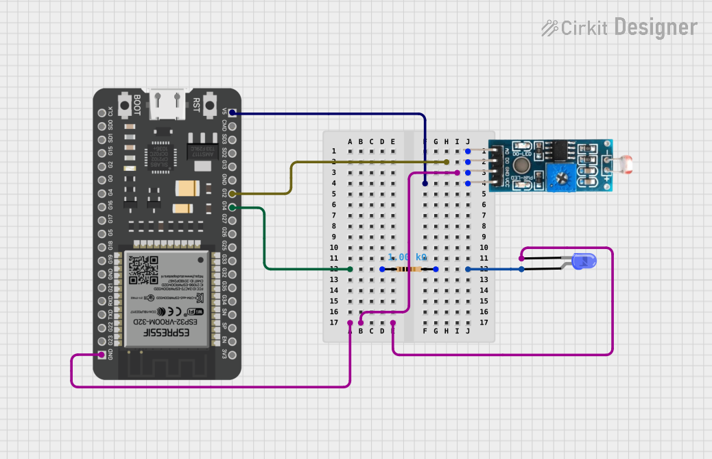
Circuit Documentation
Summary
The circuit in question appears to be a simple sensor interface circuit that utilizes an ESP32 microcontroller to read data from a light-dependent resistor (LDR) module and control an LED based on the LDR readings. The LDR module provides both digital and analog outputs, but in this circuit, only the digital output (DO) is used. The LED is connected through a resistor to limit the current. The ESP32 is powered by a 5V supply, and the LDR module is also connected to this 5V supply. The ground connections are shared among the ESP32, LDR module, and LED.
Component List
LED: Two Pin (blue)
- Pins: cathode, anode
- Description: A blue LED that emits light when a forward current passes from the anode to the cathode.
- Purpose: To provide a visual indication, typically used to represent the status of the LDR readings.
Module LDR
- Pins: VCC, GND, DO, AO
- Description: A light-dependent resistor module that changes its resistance based on the ambient light level.
- Purpose: To sense the ambient light level and provide a digital output signal that can be read by the microcontroller.
ESP32 - 38 pins
- Pins: 3V3, EN, SP, SN, G34, G35, G32, G33, G25, G26, G27, G14, G12, GND, G13, SD2, SD3, CMD, 5V, G23, G22, TXD, RXD, G21, G19, G18, G5, G17, G16, G4, G0, G2, G15, SD1, SD0, CLK
- Description: A microcontroller with Wi-Fi and Bluetooth capabilities and a wide range of GPIO pins.
- Purpose: To process the digital signal from the LDR module and control the LED accordingly.
Resistor
- Pins: pin1, pin2
- Description: A passive two-terminal electrical component that implements electrical resistance as a circuit element.
- Properties: Resistance - 1000 Ohms
- Purpose: To limit the current flowing through the LED, preventing it from being damaged.
Wiring Details
LED: Two Pin (blue)
- Cathode connected to the common ground (GND).
- Anode connected to pin2 of the Resistor.
Module LDR
- VCC connected to the 5V output of the ESP32.
- GND connected to the common ground (GND).
- DO connected to GPIO 12 (G12) of the ESP32.
ESP32 - 38 pins
- 5V providing power to the Module LDR.
- GND connected to the common ground (GND).
- G12 receiving the digital output from the Module LDR.
- G14 connected to pin1 of the Resistor.
Resistor
- Pin1 connected to GPIO 14 (G14) of the ESP32.
- Pin2 connected to the anode of the LED: Two Pin (blue).
Documented Code
Since no code was provided in the input, this section is currently empty. When code is available, it should be documented here with explanations of its functionality and how it interacts with the hardware components listed above.