Arduino-Controlled Traffic Light Simulator
Traffic Light Controller Circuit Documentation
Summary
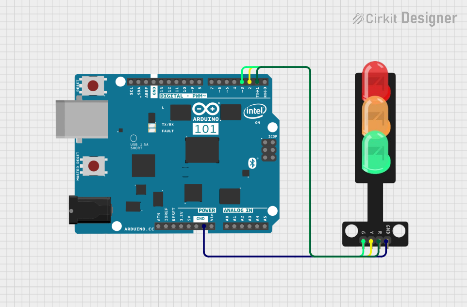
The circuit described in this documentation is designed to control a traffic light using an Arduino 101 microcontroller. The traffic light has three LEDs (Green, Yellow, and Red) that are controlled by the digital pins of the Arduino to simulate a traffic light system. The ground (GND) pin of the traffic light is connected to the GND pin of the Arduino to complete the circuit.
Component List
Traffic Light
- Pins: Green, Yellow, Red, GND
- Description: A simple traffic light component with three LEDs representing the green, yellow, and red lights.
- Purpose: To simulate a traffic light system controlled by the Arduino 101.
Arduino 101
- Pins: A5/SCL, A4/SDA, AREF, GND, D13/SCK, D12/MISO, D11 PWM/MOSI, D10 PWM/SS, D9 PWM, D8, D7, D6 PWM, D5 PWM, D4, D3 PWM, D2, D1/TX, D0/RX, AIN, ioref, RESET, 3V3, 5V, VIN, A0, A1, A2, A3, ICSP MISO, ICSP SCK, ICSP MOSI
- Description: A microcontroller board based on the Intel Curie module, designed for building IoT projects and complex algorithms due to its onboard Bluetooth LE capabilities and accelerometer/gyroscope.
- Purpose: To control the traffic light LEDs and manage the timing for the light changes.
Wiring Details
Traffic Light Wiring
- Green LED: Connected to Arduino 101 at pin D3 PWM
- Yellow LED: Connected to Arduino 101 at pin D2
- Red LED: Connected to Arduino 101 at pin D1/TX
- GND: Connected to Arduino 101 at GND pin
Arduino 101 Wiring
- D3 PWM: Connected to the Green LED of the Traffic Light
- D2: Connected to the Yellow LED of the Traffic Light
- D1/TX: Connected to the Red LED of the Traffic Light
- GND: Connected to the GND pin of the Traffic Light
Documented Code
No code has been provided for the microcontroller. To complete the documentation, the code for controlling the traffic light sequence should be included here. The code would typically initialize the digital pins connected to the LEDs as outputs and then create a loop that turns each LED on and off in sequence to simulate a traffic light.
// Example Arduino Sketch (not provided in the input)
void setup() {
  pinMode(3, OUTPUT); // Green LED
  pinMode(2, OUTPUT); // Yellow LED
  pinMode(1, OUTPUT); // Red LED
}

void loop() {
  digitalWrite(3, HIGH); // Green on
  delay(5000);           // Green for 5 seconds
  digitalWrite(3, LOW);  // Green off

  digitalWrite(2, HIGH); // Yellow on
  delay(2000);           // Yellow for 2 seconds
  digitalWrite(2, LOW);  // Yellow off

  digitalWrite(1, HIGH); // Red on
  delay(5000);           // Red for 5 seconds
  digitalWrite(1, LOW);  // Red off
}
Please note that the above code is a hypothetical example and should be replaced with the actual code intended for the Arduino 101 in this circuit.