ESP32-CAM and GPS NEO 6M Data Logger with Limit Switches
Circuit Documentation
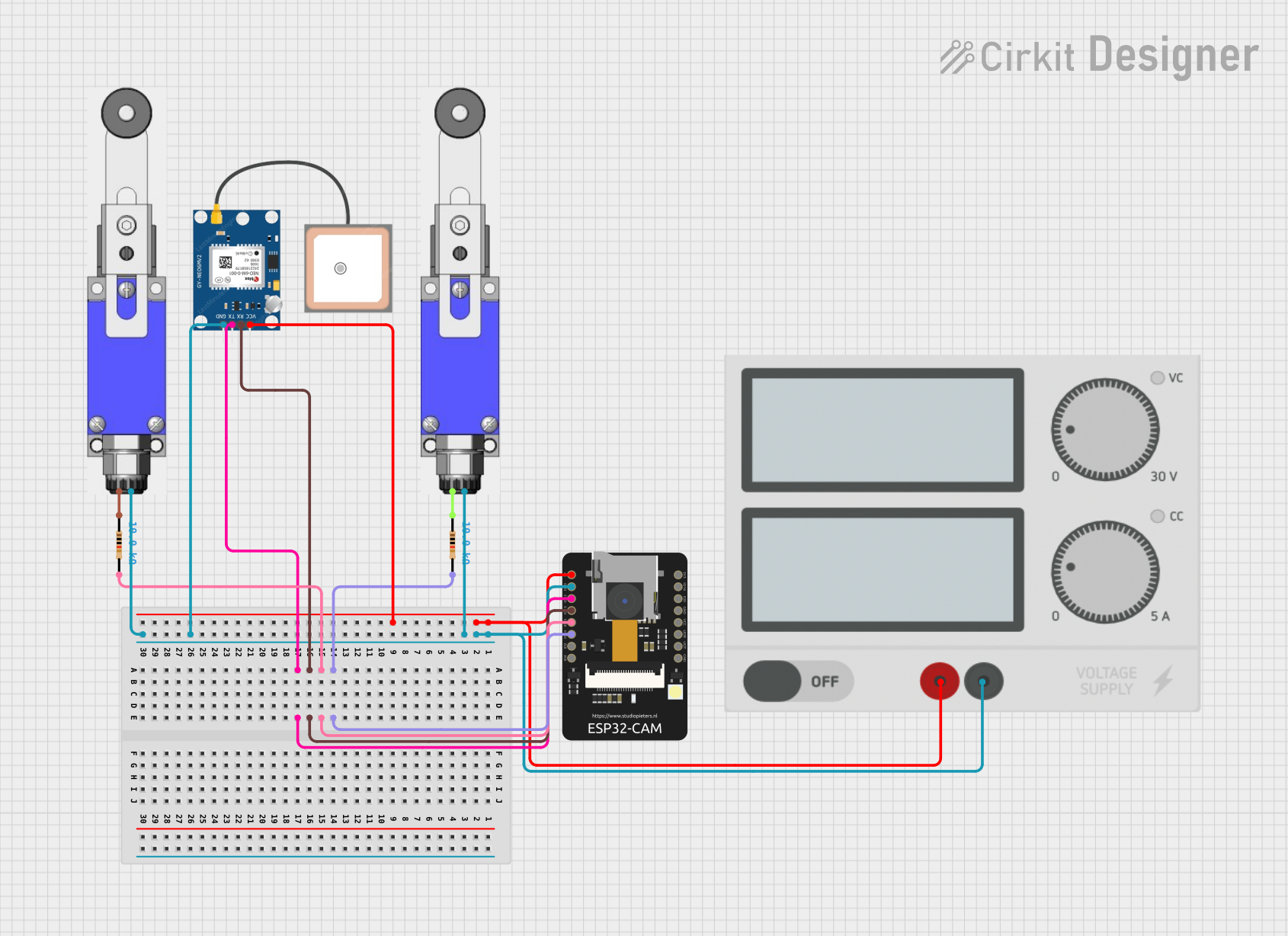
Summary of the Circuit
This circuit integrates an ESP32-CAM module with a GPS NEO 6M module, two limit switches, and a pair of resistors. The ESP32-CAM is a small camera module with Wi-Fi capabilities that can be used for various IoT applications. The GPS NEO 6M module provides location data. The limit switches are used as input devices that detect the presence or absence of an object. The resistors are likely used for pull-up or pull-down configurations to ensure proper logic levels are maintained for the inputs to the ESP32-CAM.
Component List
ESP32 - CAM
- Description: A small camera module with Wi-Fi capabilities.
- Pins: 5V, GND, IO12, IO13, IO15, IO14, IO2, IO4, VOT, VOR, VCC, IO0, IO16, 3V3
GPS NEO 6M
- Description: A GPS module that provides location data.
- Pins: VCC, RX, TX, GND
Limit Switch (x2)
- Description: A switch that is actuated by the presence or absence of an object.
- Pins: Input, Output
Power Supply
- Description: Provides power to the circuit.
- Pins: + (positive supply), - (negative supply or ground)
Resistor (x2)
- Description: A passive two-terminal electrical component that implements electrical resistance as a circuit element.
- Resistance: 10,000 Ohms (10kΩ)
Wiring Details
ESP32 - CAM
- 5V connected to the positive supply of the Power Supply.
- GND connected to the negative supply of the Power Supply and the GND pins of the GPS NEO 6M and both Limit Switches.
- IO12 connected to the TX pin of the GPS NEO 6M.
- IO13 connected to the RX pin of the GPS NEO 6M.
- IO15 connected to one end of a Resistor.
- IO14 connected to one end of another Resistor.
GPS NEO 6M
- VCC connected to the positive supply of the Power Supply.
- RX connected to IO13 of the ESP32 - CAM.
- TX connected to IO12 of the ESP32 - CAM.
- GND connected to the negative supply of the Power Supply.
Limit Switches
- The Output pin of both switches connected to the negative supply of the Power Supply.
- The Input pin of one switch connected to one end of a Resistor.
- The Input pin of the other switch connected to one end of another Resistor.
Power Supply
- (positive supply) connected to the 5V pin of the ESP32 - CAM and the VCC pin of the GPS NEO 6M.
- (negative supply) connected to the GND pins of the ESP32 - CAM, GPS NEO 6M, and both Limit Switches.
Resistors
- One end of each resistor connected to the IO15 and IO14 pins of the ESP32 - CAM, respectively.
- The other end of each resistor connected to the Input pins of the Limit Switches.
Documented Code
No code has been provided for the microcontrollers in the circuit. Therefore, this section is not applicable for the current documentation.
Please note that the actual functionality of the circuit can only be fully understood with the embedded code for the microcontroller, which is not provided in this case. The wiring details assume typical connections based on the pin labels and common practices.