
Arduino UNO-Based Optocoupler Control Circuit with Pushbutton Interface
View and Edit Project In Cirkit Designer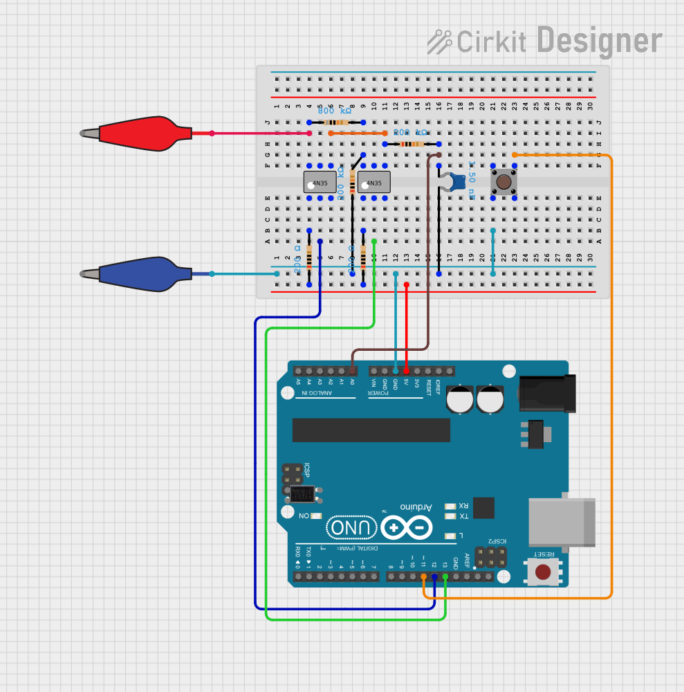
Circuit Documentation
Summary
This document provides a detailed overview of a circuit that includes an Arduino UNO microcontroller, various resistors, capacitors, pushbuttons, and optocouplers. The circuit is designed to interface with external components and perform specific functions as defined by the embedded code.
Component List
Arduino UNO
- Description: A microcontroller board based on the ATmega328P.
- Pins: UNUSED, IOREF, Reset, 3.3V, 5V, GND, Vin, A0, A1, A2, A3, A4, A5, SCL, SDA, AREF, D13, D12, D11, D10, D9, D8, D7, D6, D5, D4, D3, D2, D1, D0
Octocoupler
- Description: An optocoupler used for isolating different sections of the circuit.
- Pins: Anode, Cathode, Collector, Emitter
Alligator Clip Cable (Blue)
- Description: A cable with alligator clips for temporary connections.
- Pins: Pin, Alligator
Ceramic Capacitor
- Description: A capacitor with a capacitance of 1.5 nF.
- Pins: pin0, pin1
4N35 Optocoupler
- Description: An optocoupler used for isolating different sections of the circuit.
- Pins: Anode, Cathode, NC, Base, Collector, Emitter
Resistor (200 kΩ)
- Description: A resistor with a resistance of 200 kΩ.
- Pins: pin1, pin2
Resistor (200 Ω)
- Description: A resistor with a resistance of 200 Ω.
- Pins: pin1, pin2
Resistor (800 kΩ)
- Description: A resistor with a resistance of 800 kΩ.
- Pins: pin1, pin2
Pushbutton
- Description: A pushbutton switch.
- Pins: Pin 3 (out), Pin 4 (out), Pin 1 (in), Pin 2 (in)
Alligator Clip Cable (Red)
- Description: A cable with alligator clips for temporary connections.
- Pins: Pin, Alligator
Wiring Details
Arduino UNO
- D12: Connected to Cathode of 4N35 Optocoupler
- D13: Connected to Cathode of another 4N35 Optocoupler
- A0: Connected to pin0 of Ceramic Capacitor and pin2 of a Resistor
- D11: Connected to Pin 3 (out) of Pushbutton
- 5V: Connected to pin1 of two Resistors
- GND: Connected to pin1 of Ceramic Capacitor, pin1 of a Resistor, Pin 2 (in) of Pushbutton, and Pin of Alligator Clip Cable (Blue)
4N35 Optocoupler
- Base: Connected to pin1 of 800 kΩ Resistor and Pin of Alligator Clip Cable (Red)
- Cathode: Connected to D12 of Arduino UNO
- Emitter: Connected to pin1 of 200 kΩ Resistor and Emitter of another 4N35 Optocoupler
- Anode: Connected to pin2 of 200 Ω Resistor
Another 4N35 Optocoupler
- Base: Connected to pin2 of 200 kΩ Resistor and pin2 of 800 kΩ Resistor
- Cathode: Connected to D13 of Arduino UNO
- Emitter: Connected to pin1 of 200 kΩ Resistor and Emitter of another 4N35 Optocoupler
- Anode: Connected to pin2 of 200 Ω Resistor
Ceramic Capacitor
- pin0: Connected to A0 of Arduino UNO and pin2 of a Resistor
- pin1: Connected to pin1 of a Resistor, Pin 2 (in) of Pushbutton, and Pin of Alligator Clip Cable (Blue)
Resistor (200 kΩ)
- pin1: Connected to Base of 4N35 Optocoupler and Pin of Alligator Clip Cable (Red)
- pin2: Connected to Base of another 4N35 Optocoupler and pin2 of 800 kΩ Resistor
Resistor (200 Ω)
- pin1: Connected to 5V of Arduino UNO
- pin2: Connected to Anode of 4N35 Optocoupler
Resistor (800 kΩ)
- pin1: Connected to Base of 4N35 Optocoupler and Pin of Alligator Clip Cable (Red)
- pin2: Connected to Base of another 4N35 Optocoupler and pin2 of 200 kΩ Resistor
Pushbutton
- Pin 3 (out): Connected to D11 of Arduino UNO
- Pin 2 (in): Connected to pin1 of Ceramic Capacitor, pin1 of a Resistor, and Pin of Alligator Clip Cable (Blue)
Alligator Clip Cable (Blue)
- Pin: Connected to GND of Arduino UNO, pin1 of Ceramic Capacitor, pin1 of a Resistor, and Pin 2 (in) of Pushbutton
Alligator Clip Cable (Red)
- Pin: Connected to Base of 4N35 Optocoupler and pin1 of 800 kΩ Resistor
Code Documentation
Arduino UNO Code
void setup() {
  // put your setup code here, to run once:

}

void loop() {
  // put your main code here, to run repeatedly:

}
This code is a basic template for the Arduino UNO. The setup function is called once when the program starts and is used to initialize variables, pin modes, start using libraries, etc. The loop function runs continuously after the setup function has completed. This is where the main logic of the program is implemented.