
ESP32 and GPS NEO 6M Powered Battery-Operated TFT Display System
View and Edit Project In Cirkit Designer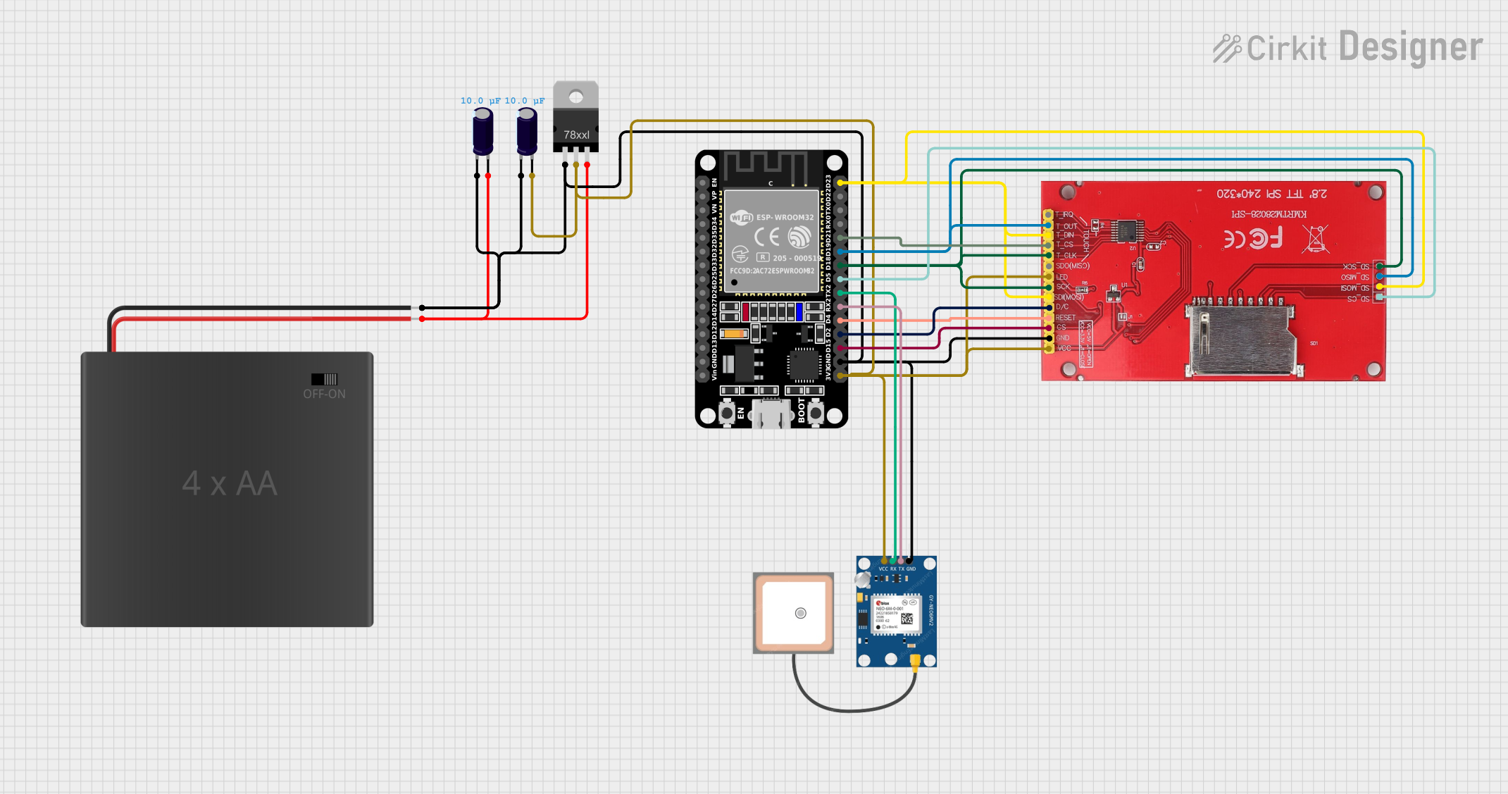
Circuit Documentation
Summary
This document provides a detailed overview of a circuit that includes an ILI9341 TFT display, a GPS NEO 6M module, a 4xAA battery pack, a voltage regulator (LD1117VXX), electrolytic capacitors, and an ESP32 microcontroller. The circuit is designed to interface the TFT display and GPS module with the ESP32, powered by a 4xAA battery pack through a voltage regulator.
Component List
ILI9341 TFT Display
- Pins: SD_CS, SD_MOSI, SD_MISO, SD_SCK, VCC, GND, CS, RESET, D/C, SD(MOSI), SCK, LED, SDO(MISO), T_CLK, T_CS, T_DIN, T_OUT, T_IRQ
- Description: A 2.8-inch TFT display with touch functionality.
GPS NEO 6M
- Pins: VCC, RX, TX, GND
- Description: A GPS module for receiving location data.
4xAA Battery Pack
- Pins: POS, NEG
- Description: A battery pack holding four AA batteries to power the circuit.
Voltage Regulator (LD1117VXX)
- Pins: GND, OUT, IN
- Description: A voltage regulator to step down the voltage from the battery pack to a stable 3.3V.
Electrolytic Capacitor (10µF)
- Pins: -, +
- Description: Capacitors used for power supply smoothing.
- Capacitance: 10µF
ESP32 (30 pin)
- Pins: EN, VP, VN, D34, D35, D32, D33, D25, D26, D27, D14, D12, D13, GND, Vin, D23, D22, TX0, RX0, D21, D19, D18, D5, TX2, RX2, D4, D2, D15, 3V3
- Description: A powerful microcontroller with Wi-Fi and Bluetooth capabilities.
Wiring Details
ILI9341 TFT Display
- SD_MOSI, T_DIN, SD(MOSI) connected to ESP32 D23
- T_CS connected to ESP32 D21
- T_OUT, SD_MISO connected to ESP32 D19
- SCK, T_CLK, SD_SCK connected to ESP32 D18
- SD_CS connected to ESP32 D5
- RESET connected to ESP32 D4
- D/C connected to ESP32 D2
- CS connected to ESP32 D15
- GND connected to common ground
- VCC, LED connected to 3.3V from the voltage regulator
GPS NEO 6M
- RX connected to ESP32 TX2
- TX connected to ESP32 RX2
- GND connected to common ground
- VCC connected to 3.3V from the voltage regulator
4xAA Battery Pack
- POS connected to Voltage Regulator IN and Electrolytic Capacitor +
- NEG connected to common ground
Voltage Regulator (LD1117VXX)
- IN connected to 4xAA Battery Pack POS and Electrolytic Capacitor +
- OUT connected to Electrolytic Capacitor +, GPS NEO 6M VCC, ILI9341 TFT Display VCC, ILI9341 TFT Display LED, and ESP32 3V3
- GND connected to common ground
Electrolytic Capacitors
- First Capacitor (-) connected to common ground
- First Capacitor (+) connected to Voltage Regulator IN and 4xAA Battery Pack POS
- Second Capacitor (-) connected to common ground
- Second Capacitor (+) connected to Voltage Regulator OUT
ESP32 (30 pin)
- D23 connected to ILI9341 TFT Display SD_MOSI, T_DIN, SD(MOSI)
- D21 connected to ILI9341 TFT Display T_CS
- D19 connected to ILI9341 TFT Display T_OUT, SD_MISO
- D18 connected to ILI9341 TFT Display SCK, T_CLK, SD_SCK
- D5 connected to ILI9341 TFT Display SD_CS
- TX2 connected to GPS NEO 6M RX
- RX2 connected to GPS NEO 6M TX
- D4 connected to ILI9341 TFT Display RESET
- D2 connected to ILI9341 TFT Display D/C
- D15 connected to ILI9341 TFT Display CS
- GND connected to common ground
- 3V3 connected to Voltage Regulator OUT
Code
No code provided for this circuit.
This document provides a comprehensive overview of the circuit, including a summary, component list, wiring details, and code section. Each component is described, and the wiring details ensure proper connections for the circuit to function as intended.