
ESP32-Based Dual CAN Bus Data Logger with Wireless Sensor Integration
View and Edit Project In Cirkit Designer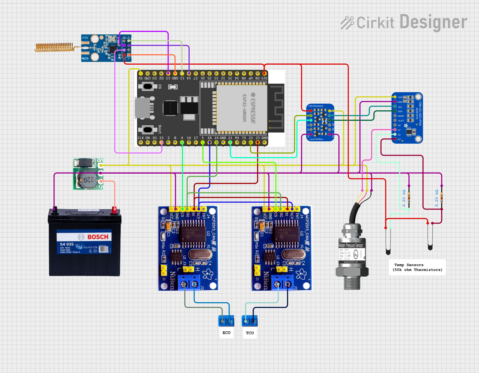
Circuit Documentation
Summary
This circuit is designed to interface with two CAN networks using MCP2515 controllers, read data from various sensors via an ADS1015 ADC, and transmit the collected data using ESP-NOW to another ESP32 connected to a display. The circuit includes components such as an ESP32 microcontroller, MCP2515 CAN controllers, an ADS1015 ADC, a water pressure sensor, NTC thermistors, resistors, a logic level converter, and a power supply system.
Component List
Gravity: Analog Water Pressure Sensor
- Description: Measures water pressure and outputs an analog signal.
- Pins: Signal, VCC, GND
NTC (Negative Temperature Coefficient) Thermistor
- Description: Measures temperature by changing resistance with temperature.
- Pins: A0, A1
Resistor
- Description: Provides a fixed resistance in the circuit.
- Pins: pin1, pin2
- Properties:
- Resistance: 6200 Ohms
Adafruit 4-channel I2C-safe Bi-directional Logic Level Converter
- Description: Converts logic levels between different voltage systems.
- Pins: GND, A4, A3, A2, A1, LV, B4, B3, B2, B1, HV
Adafruit ADS1015 12Bit I2C ADC
- Description: Converts analog signals to digital data.
- Pins: VDD, GND, SCL, SDA, ADDR, ALERT, AIN0, AIN1, AIN2, AIN3
Terminal PCB 2 Pin
- Description: Provides a terminal connection for external components.
- Pins: Pin A, Pin B
CC1101
- Description: RF transceiver for wireless communication.
- Pins: VCC, GND, GDO0, SCLK, SO, GDO2, SI, CSN
12V 200Ah Battery
- Description: Provides power to the circuit.
- Pins: GND, 12V
MCP2515
- Description: CAN controller for interfacing with CAN networks.
- Pins: INT, SCK, SI, SO, CS, GND, VCC, H, L
DD4012SA
- Description: DC-DC converter for voltage regulation.
- Pins: Vin, GND, Vout
ESP 32 Wroom Dev Kit
- Description: Microcontroller with Wi-Fi and Bluetooth capabilities.
- Pins: 3V3, EN, VP, VN, GPIO 34, GPIO 35, GPIO 32, GPIO 33, GPIO 25, GPIO 26, GPIO 27, GPIO 14, GND, GPIO 13, SD2, SD3, CMD, V5, GPIO 23, GPIO 22, TXD, RXD, GPIO 21, GPIO 19, GPIO 18, GPIO 5, GPIO 17, GPIO 16, GPIO 4, GPIO 0, GPIO 2, GPIO 15, SD1, SD0, CLK
Wiring Details
Gravity: Analog Water Pressure Sensor
- VCC connected to V5 of ESP 32 Wroom Dev Kit
- GND connected to GND of 12V 200Ah Battery
- Signal connected to AIN1 of Adafruit ADS1015 12Bit I2C ADC
NTC Thermistor (Instance 1)
- A0 connected to AIN2 of Adafruit ADS1015 12Bit I2C ADC
- A1 connected to LV of Adafruit 4-channel I2C-safe Bi-directional Logic Level Converter
NTC Thermistor (Instance 2)
- A0 connected to AIN3 of Adafruit ADS1015 12Bit I2C ADC
- A1 connected to LV of Adafruit 4-channel I2C-safe Bi-directional Logic Level Converter
Resistor (Instance 1)
- pin1 connected to A0 of NTC Thermistor (Instance 1)
- pin2 connected to GND of 12V 200Ah Battery
Resistor (Instance 2)
- pin1 connected to A0 of NTC Thermistor (Instance 2)
- pin2 connected to GND of 12V 200Ah Battery
Adafruit 4-channel I2C-safe Bi-directional Logic Level Converter
- HV connected to V5 of ESP 32 Wroom Dev Kit
- GND connected to GND of 12V 200Ah Battery
- B1 connected to SCL of Adafruit ADS1015 12Bit I2C ADC
- B2 connected to SDA of Adafruit ADS1015 12Bit I2C ADC
- A1 connected to GPIO 22 of ESP 32 Wroom Dev Kit
- A2 connected to GPIO 21 of ESP 32 Wroom Dev Kit
- LV connected to 3V3 of ESP 32 Wroom Dev Kit
Adafruit ADS1015 12Bit I2C ADC
- VDD connected to V5 of ESP 32 Wroom Dev Kit
- GND connected to GND of 12V 200Ah Battery
- SCL connected to B1 of Adafruit 4-channel I2C-safe Bi-directional Logic Level Converter
- SDA connected to B2 of Adafruit 4-channel I2C-safe Bi-directional Logic Level Converter
- AIN1 connected to Signal of Gravity: Analog Water Pressure Sensor
- AIN2 connected to A0 of NTC Thermistor (Instance 1)
- AIN3 connected to A0 of NTC Thermistor (Instance 2)
Terminal PCB 2 Pin (Instance 1)
- Pin A connected to L of MCP2515 (Instance 1)
- Pin B connected to H of MCP2515 (Instance 1)
Terminal PCB 2 Pin (Instance 2)
- Pin A connected to L of MCP2515 (Instance 2)
- Pin B connected to H of MCP2515 (Instance 2)
CC1101
- VCC connected to 3V3 of ESP 32 Wroom Dev Kit
- GND connected to GND of ESP 32 Wroom Dev Kit
- SCLK connected to GPIO 14 of ESP 32 Wroom Dev Kit
- SO connected to GPIO 14 of ESP 32 Wroom Dev Kit
- SI connected to GPIO 13 of ESP 32 Wroom Dev Kit
- CSN connected to GPIO 15 of ESP 32 Wroom Dev Kit
12V 200Ah Battery
- 12V connected to Vin of DD4012SA
- GND connected to GND of DD4012SA
MCP2515 (Instance 1)
- VCC connected to V5 of ESP 32 Wroom Dev Kit
- GND connected to GND of 12V 200Ah Battery
- SCK connected to GPIO 18 of ESP 32 Wroom Dev Kit
- SI connected to GPIO 23 of ESP 32 Wroom Dev Kit
- SO connected to GPIO 19 of ESP 32 Wroom Dev Kit
- CS connected to GPIO 5 of ESP 32 Wroom Dev Kit
- H connected to Pin B of Terminal PCB 2 Pin (Instance 1)
- L connected to Pin A of Terminal PCB 2 Pin (Instance 1)
MCP2515 (Instance 2)
- VCC connected to V5 of ESP 32 Wroom Dev Kit
- GND connected to GND of 12V 200Ah Battery
- SCK connected to GPIO 18 of ESP 32 Wroom Dev Kit
- SI connected to GPIO 23 of ESP 32 Wroom Dev Kit
- SO connected to GPIO 19 of ESP 32 Wroom Dev Kit
- CS connected to GPIO 4 of ESP 32 Wroom Dev Kit
- H connected to Pin B of Terminal PCB 2 Pin (Instance 2)
- L connected