Cirkit Designer
Your all-in-one circuit design IDE
Home /
Project Documentation
ESP32-Based Battery-Powered Smart Temperature and Touch Display
Circuit Documentation
Summary
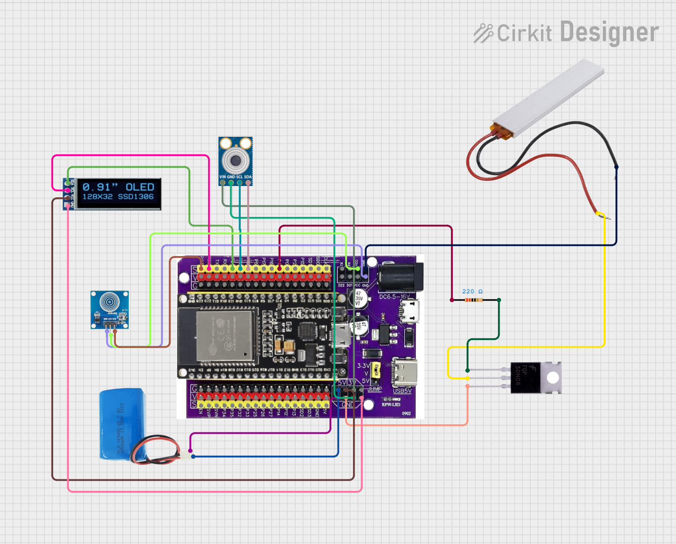
This document provides a detailed overview of a circuit that includes an ESP32 microcontroller, a PTC, an MLX90614 temperature sensor, an OLED display, a touch sensor, a 5V battery, a MOSFET, and a resistor. The circuit is designed to interface various sensors and display data on an OLED screen, with power management and protection components.
Component List
ESP32 on Baseboard
- Description: A versatile microcontroller with multiple GPIO pins.
- Pins: GPIO23, GPIO22, GPIO1/TX, GPIO3/RX, GPIO21, GPIO19, GPIO18, GPIO5, GPIO17, GPIO16, GPIO4, GPIO0, GPIO2, GPIO15, SD1, SD0, CLK, V, G, GPIO36, GPIO39, GPIO34, GPIO35, GPIO32, GPIO33, GPIO25, GPIO26, GPIO27, GPIO14, GPIO12, GPIO13, SD2, SD3, GND, 5V, 3V, TX, RX, VCC, D22, D21
PTC
- Description: A positive temperature coefficient thermistor used for overcurrent protection.
- Pins: Neutral, Live
MLX90614
- Description: An infrared temperature sensor.
- Pins: SDA, SCL, GND, VIN
OLED Display 128x32
- Description: A small OLED display for visual output.
- Pins: SDA, SCL, VCC, GND
Touch Sensor
- Description: A capacitive touch sensor.
- Pins: IO, VCC, GND
5V Battery
- Description: A power source for the circuit.
- Pins: Positive, Negative
MOSFET
- Description: A type of transistor used for switching and amplification.
- Pins: Gate, Drain, Source
Resistor
- Description: A 220 Ohm resistor.
- Pins: Pin1, Pin2
- Properties: Resistance: 220 Ohms
Wiring Details
ESP32 on Baseboard
- GPIO23 is connected to IO of the Touch Sensor.
- GPIO22 is connected to SCL of the OLED Display.
- GPIO21 is connected to SDA of the OLED Display.
- GPIO19 is connected to SCL of the MLX90614.
- GPIO18 is connected to SDA of the MLX90614.
- GPIO4 is connected to Pin1 of the Resistor.
- GND is connected to:
- Negative of the 5V Battery
- Source of the MOSFET
- GND of the MLX90614
- GND of the OLED Display
- Neutral of the PTC
- GND of the Touch Sensor
- 5V is connected to:
- Positive of the 5V Battery
- VCC of the OLED Display
- 3V is connected to VIN of the MLX90614.
- VCC is connected to VCC of the Touch Sensor.
PTC
- Neutral is connected to GND of the ESP32 on Baseboard.
- Live is connected to Drain of the MOSFET.
MLX90614
- SDA is connected to GPIO18 of the ESP32 on Baseboard.
- SCL is connected to GPIO19 of the ESP32 on Baseboard.
- GND is connected to GND of the ESP32 on Baseboard.
- VIN is connected to 3V of the ESP32 on Baseboard.
OLED Display 128x32
- SCL is connected to GPIO22 of the ESP32 on Baseboard.
- SDA is connected to GPIO21 of the ESP32 on Baseboard.
- VCC is connected to 5V of the ESP32 on Baseboard.
- GND is connected to GND of the ESP32 on Baseboard.
Touch Sensor
- IO is connected to GPIO23 of the ESP32 on Baseboard.
- VCC is connected to VCC of the ESP32 on Baseboard.
- GND is connected to GND of the ESP32 on Baseboard.
5V Battery
- Positive is connected to 5V of the ESP32 on Baseboard.
- Negative is connected to GND of the ESP32 on Baseboard.
MOSFET
- Gate is connected to Pin2 of the Resistor.
- Drain is connected to Live of the PTC.
- Source is connected to GND of the ESP32 on Baseboard.
Resistor
- Pin1 is connected to GPIO4 of the ESP32 on Baseboard.
- Pin2 is connected to Gate of the MOSFET.
Code
No code is provided for this circuit.