
Battery-Powered DC-DC Converter System for Multi-Voltage Power Distribution
View and Edit Project In Cirkit Designer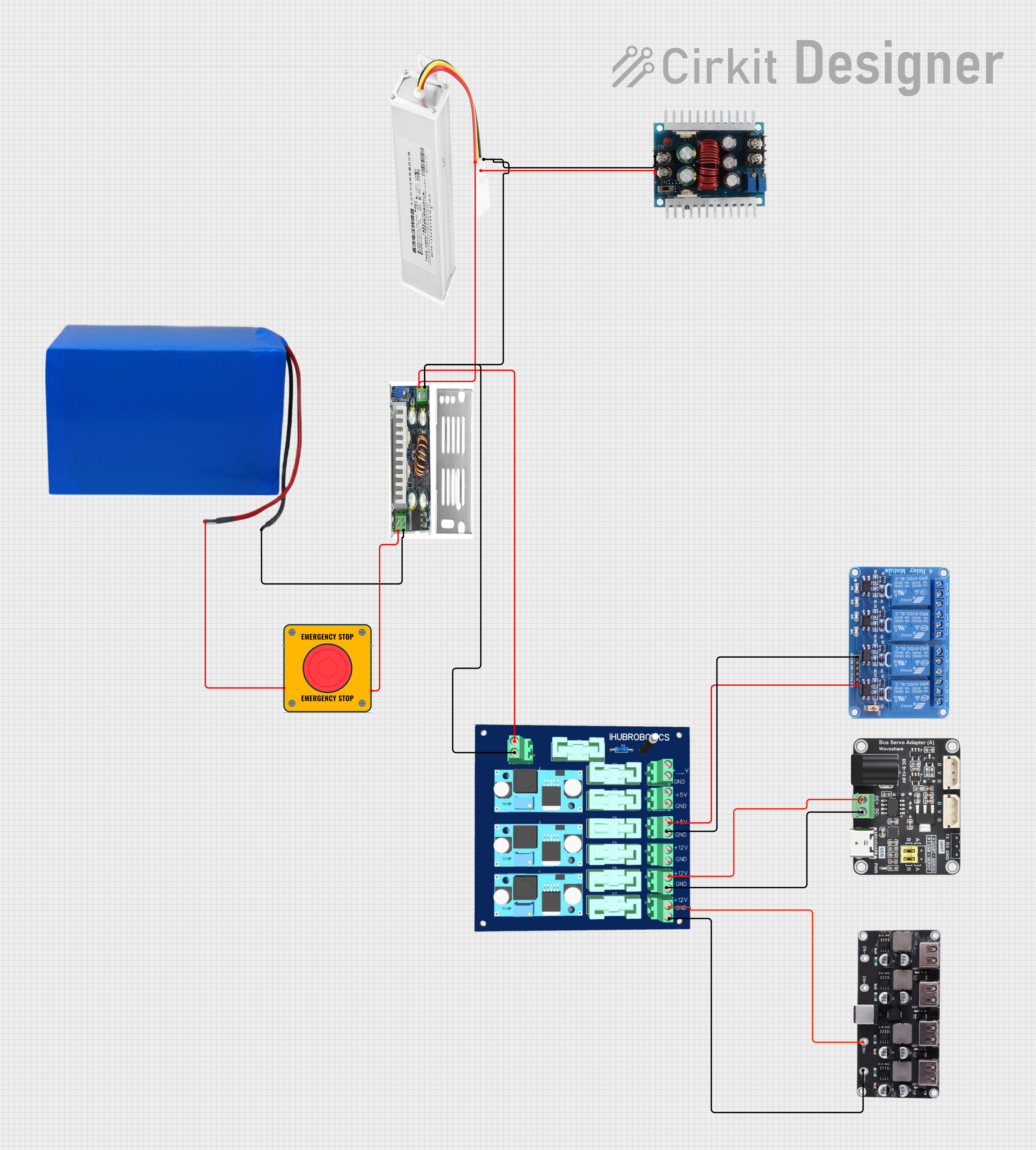
Circuit Documentation
Summary
This document provides a detailed overview of a circuit comprising various DC-DC converters, a battery, a bus servo adaptor, an emergency stop switch, a USB power module, a relay module, and a power module. The circuit is designed to manage power distribution and control for various components, ensuring regulated voltage levels and safe operation.
Component List
DC-DC Converter
- Description: Converts DC voltage from one level to another.
- Pins: Out +ve, Out -ve, In +ve, In -ve
36V-72V DC to 12V 15A Converter
- Description: Converts a high DC voltage (36V-72V) to a stable 12V output at 15A.
- Pins: Vin Red, 12V Yellow, Gnd Black
6V-40V DC to 1.2V-36V Converter
- Description: Converts a DC voltage within the range of 6V-40V to a variable output between 1.2V and 36V.
- Pins: In +ve, In -ve, Out -ve, Out +ve
Battery 38.5V 24Ah
- Description: Provides a 38.5V DC power source with a capacity of 24Ah.
- Pins: Out +ve, Out -ve
Bus Servo Adaptor
- Description: Adapts power and signal for bus servos.
- Pins: Servo Din, Servo Vcc, Servo Gnd, In +ve, In -ve, Signal USB
E Stop
- Description: Emergency stop switch for safety.
- Pins: NO 1, NO 2, NC 1, NC 2
4 Channel USB 5V
- Description: Provides 5V power to four USB channels.
- Pins: usb 1, usb 2, usb 3, usb 4, In +ve, In -ve
Relay 4 Channel 5V
- Description: 4-channel relay module operating at 5V.
- Pins: GND, IN1, IN2, IN3, IN4, VCC, COM1, COM2, COM3, COM4, NO1, NO2, NO3, NO4, NC1, NC2, NC3, NC4
Power Module 6 Channel
- Description: Distributes power to multiple channels with different voltage levels.
- Pins: In +ve, In -ve, 5V +ve, 12V +ve, 5V Gnd, 12V Gnd
Wiring Details
DC-DC Converter
Out +ve connected to:
- Vin Red of 36V-72V DC to 12V 15A Converter
- In +ve of Power Module 6 Channel
Out -ve connected to:
- Gnd Black of 36V-72V DC to 12V 15A Converter
- In -ve of 6V-40V DC to 1.2V-36V Converter
- In -ve of Power Module 6 Channel
In +ve connected to:
- NC 2 of E Stop
In -ve connected to:
- Out -ve of Battery 38.5V 24Ah
36V-72V DC to 12V 15A Converter
Vin Red connected to:
- Out +ve of DC-DC Converter
- In +ve of Power Module 6 Channel
12V Yellow connected to:
- In +ve of 6V-40V DC to 1.2V-36V Converter
Gnd Black connected to:
- Out -ve of DC-DC Converter
- In -ve of 6V-40V DC to 1.2V-36V Converter
- In -ve of Power Module 6 Channel
6V-40V DC to 1.2V-36V Converter
In +ve connected to:
- 12V Yellow of 36V-72V DC to 12V 15A Converter
In -ve connected to:
- Gnd Black of 36V-72V DC to 12V 15A Converter
- Out -ve of DC-DC Converter
- In -ve of Power Module 6 Channel
Battery 38.5V 24Ah
Out +ve connected to:
- NC 1 of E Stop
Out -ve connected to:
- In -ve of DC-DC Converter
Bus Servo Adaptor
In +ve connected to:
- 12V +ve of Power Module 6 Channel
In -ve connected to:
- 12V Gnd of Power Module 6 Channel
E Stop
NC 1 connected to:
- Out +ve of Battery 38.5V 24Ah
NC 2 connected to:
- In +ve of DC-DC Converter
4 Channel USB 5V
In +ve connected to:
- 12V +ve of Power Module 6 Channel
In -ve connected to:
- 12V Gnd of Power Module 6 Channel
Relay 4 Channel 5V
VCC connected to:
- 5V +ve of Power Module 6 Channel
GND connected to:
- 5V Gnd of Power Module 6 Channel
Power Module 6 Channel
In +ve connected to:
- Out +ve of DC-DC Converter
- Vin Red of 36V-72V DC to 12V 15A Converter
In -ve connected to:
- Out -ve of DC-DC Converter
- Gnd Black of 36V-72V DC to 12V 15A Converter
- In -ve of 6V-40V DC to 1.2V-36V Converter
5V +ve connected to:
- VCC of Relay 4 Channel 5V
12V +ve connected to:
- In +ve of Bus Servo Adaptor
- In +ve of 4 Channel USB 5V
5V Gnd connected to:
- GND of Relay 4 Channel 5V
12V Gnd connected to:
- In -ve of Bus Servo Adaptor
- In -ve of 4 Channel USB 5V
Code
No microcontroller code is provided for this circuit.