
Arduino Mega 2560 Controlled 4-Wheel Line Following Robot with IR Sensors and L298N Motor Drivers
View and Edit Project In Cirkit Designer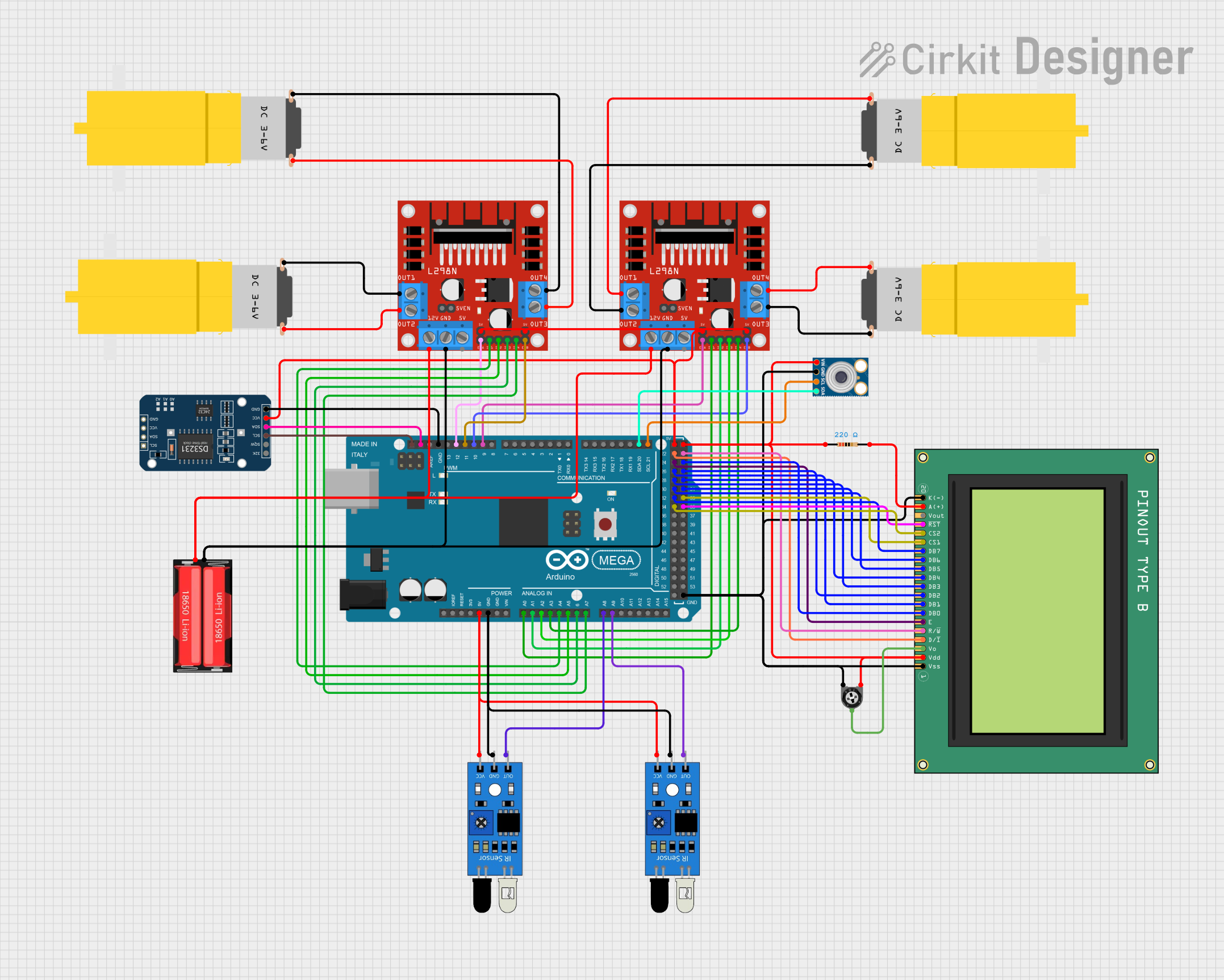
Circuit Documentation
Summary
The circuit is designed to control a 4-wheel line-following robot using an Arduino Mega 2560 as the central processing unit. The robot utilizes two L298N motor drivers to control four yellow hobby gear motors, and it detects the line using two IR sensors. Additionally, the circuit includes an MLX90614 infrared thermometer for temperature sensing, a DS3231 Real-Time Clock (RTC) for timekeeping, a Graphic LCD Display (GLCD 128x64) for visual output, and power is supplied by an 18650 Li-Ion battery. The circuit also features a resistor and a trimmer potentiometer for voltage adjustments.
Component List
Microcontroller
- Arduino Mega 2560: A microcontroller board based on the ATmega2560, with a wide range of input/output pins, including analog, digital, PWM, and I2C.
Motors
- Motor Amarillo Motorreductor Hobby: Four DC gear motors used for driving the robot's wheels.
Motor Drivers
- L298N DC Motor Driver: Two motor driver modules capable of driving up to two DC motors each, with direction and speed control via the Arduino.
Sensors
- IR Sensor: Two infrared sensors used for line detection on the robot's path.
- MLX90614: An infrared thermometer for non-contact temperature measurements.
- DS3231 RTC: A real-time clock module for maintaining accurate time.
Display
- Graphic LCD Display (GLCD 128x64): A graphical display for visual output, such as sensor readings or status information.
Power Supply
- 18650 Li-Ion Battery: A rechargeable battery providing the power source for the motor drivers and the entire circuit.
Passive Components
- Resistor (220 Ohms): A resistor used for current limiting, possibly for the GLCD backlight.
- Trimmer Potentiometer (10k Ohms): A variable resistor for adjusting voltage, likely used for the GLCD contrast control.
Wiring Details
Arduino Mega 2560
- 5V & GND: Powers the IR sensors, MLX90614, DS3231 RTC, and the L298N motor drivers' logic.
- A0 - A7: Control signals for the L298N motor drivers (IN1-IN4 for each driver).
- A8 & A9: Input from the IR sensors.
- D9 & D10 (PWM): PWM outputs to control the speed of the motors via ENA and ENB on the first L298N motor driver.
- D11 & D12 (PWM): PWM outputs to control the speed of the motors via ENA2 and ENB2 on the second L298N motor driver.
- D20/SDA & D21/SCL: I2C communication with the MLX90614 and DS3231 RTC.
- D22 - D35: Control signals for the GLCD.
Motor Amarillo Motorreductor Hobby
- vcc & GND: Connected to the output pins of the L298N motor drivers to control the motor's direction and speed.
L298N DC Motor Driver
- IN1 - IN4: Control signals from the Arduino for motor direction.
- ENA & ENB: PWM signals from the Arduino to control motor speed.
- OUT1 - OUT4: Outputs to the motors.
- 12V & GND: Power input from the 18650 Li-Ion battery.
IR Sensor
- vcc & GND: Power supply from the Arduino.
- out: Signal output connected to the Arduino's analog pins for line detection.
MLX90614
- VIN & GND: Power supply from the Arduino.
- SDA & SCL: I2C communication with the Arduino.
DS3231 RTC
- VCC & GND: Power supply from the Arduino.
- SDA & SCL: I2C communication with the Arduino.
Graphic LCD Display (GLCD 128x64)
- Control and Data Pins (D22 - D35): Connected to the corresponding pins on the Arduino for display control.
- Vdd & Vss: Power supply and ground.
- Vo: Contrast adjustment connected to the wiper of the trimmer potentiometer.
- A(+) & K(-): Backlight power supply, with the anode connected through a resistor.
Resistor
- pin1 & pin2: Connected between the GLCD backlight anode and power supply.
Trimmer Potentiometer
- leg1 & leg2: Ends connected to the power supply and ground.
- wiper: Connected to the GLCD contrast adjustment pin.
18650 Li-Ion Battery
- Positive & Negative: Power supply to the L298N motor drivers.
Documented Code
/*
 * Arduino Sketch for 4-Wheel Line Following Robot
 *
 * This code controls a 4-wheel robot that follows a line using IR sensors.
 * The robot uses two L298N motor drivers to control the motors and IR sensors
 * to detect the line. The motors are connected to the motor drivers, which are
 * controlled by the Arduino Mega 2560. The IR sensors provide input to the
 * Arduino to determine the position of the line.
 */

// Pin definitions
#define ENA 9
#define ENB 10
#define IN1 A0
#define IN2 A1
#define IN3 A2
#define IN4 A3
#define ENA2 11
#define ENB2 12
#define IN1_2 A4
#define IN2_2 A5
#define IN3_2 A6
#define IN4_2 A7
#define IR_LEFT A8
#define IR_RIGHT A9

void setup() {
  // Initialize motor control pins
  pinMode(ENA, OUTPUT);
  pinMode(ENB, OUTPUT);
  pinMode(IN1, OUTPUT);
  pinMode(IN2, OUTPUT);
  pinMode(IN3, OUTPUT);
  pinMode(IN4, OUTPUT);
  pinMode(ENA2, OUTPUT);
  pinMode(ENB2, OUTPUT);
  pinMode(IN1_2, OUTPUT);
  pinMode(IN2_2, OUTPUT);
  pinMode(IN3_2, OUTPUT);
  pinMode(IN4_2, OUTPUT);
  // Initialize IR sensor pins
  pinMode(IR_LEFT, INPUT);
  pinMode(IR_RIGHT, INPUT);
}

void loop() {
  // Read IR sensor values
  int leftSensor = digitalRead(IR_LEFT);
  int rightSensor = digitalRead(IR_RIGHT);

  // Determine motor actions based on sensor values
  if (leftSensor == HIGH && rightSensor == LOW) {
    // Turn right
    moveRight();
  } else if (leftSensor == LOW && rightSensor == HIGH) {
    // Turn left
    moveLeft();
  } else if (leftSensor == LOW && rightSensor == LOW) {
    // Move forward
    moveForward();
  } else {
    // Stop
    stopMotors();
  }
}

void moveForward() {
  digitalWrite(IN1, HIGH);
  digitalWrite(IN2, LOW);
  digitalWrite(IN3, HIGH);
  digitalWrite(IN4, LOW);
  digitalWrite(IN1_2, HIGH);
  digitalWrite(IN2_2, LOW);
  digitalWrite(IN3_2, HIGH);
  digitalWrite(IN4_2, LOW);
  analogWrite(ENA, 255);
  analogWrite(ENB, 255);
  analogWrite(ENA2, 255);
  analogWrite(ENB2, 255);
}

void moveLeft() {
  digitalWrite(IN1, LOW);
  digitalWrite(IN2, HIGH);
  digitalWrite(IN3, HIGH);
  digitalWrite(IN4, LOW);
  digitalWrite(IN1_2, LOW);
  digitalWrite(IN2_2, HIGH);
  digitalWrite(IN3_2, HIGH);
  digitalWrite(IN4_2, LOW);
  analogWrite(ENA, 255);
  analogWrite(ENB, 255);
  analogWrite(ENA2, 255);
  analogWrite(ENB2, 255);
}

void moveRight() {
  digitalWrite(IN1, HIGH);
  digitalWrite(IN2, LOW);
  digitalWrite(IN3, LOW);
  digitalWrite(IN4, HIGH);
  digitalWrite(IN1_2, HIGH);
  digitalWrite(IN2_2, LOW);
  digitalWrite(IN3_2, LOW);
  digitalWrite(IN4_2, HIGH);
  analogWrite(ENA, 255);
  analogWrite(ENB, 255);
  analogWrite(ENA2, 255);
  analogWrite(ENB2, 255);
}

void stopMotors() {
  digitalWrite(IN1, LOW);
  digitalWrite(IN2, LOW);
  digitalWrite(IN3, LOW);
  digitalWrite(IN4, LOW);
  digitalWrite(IN1_2, LOW);
  digitalWrite(IN2_2, LOW);
  digitalWrite(IN3_2, LOW);
  digitalWrite(IN4_2, LOW);
  analogWrite(ENA, 0);
  analogWrite(ENB, 0);
  analogWrite(ENA2, 0);
  analogWrite(ENB2, 0);
}
This code is responsible for controlling the robot's movement based on the input from the IR sensors. It sets up the necessary pins as inputs or outputs and contains functions to move the robot forward, left, right, or stop it entirely. The IR sensors' readings determine the robot's direction, while the motor drivers receive signals from the Arduino to control the motors' speed and