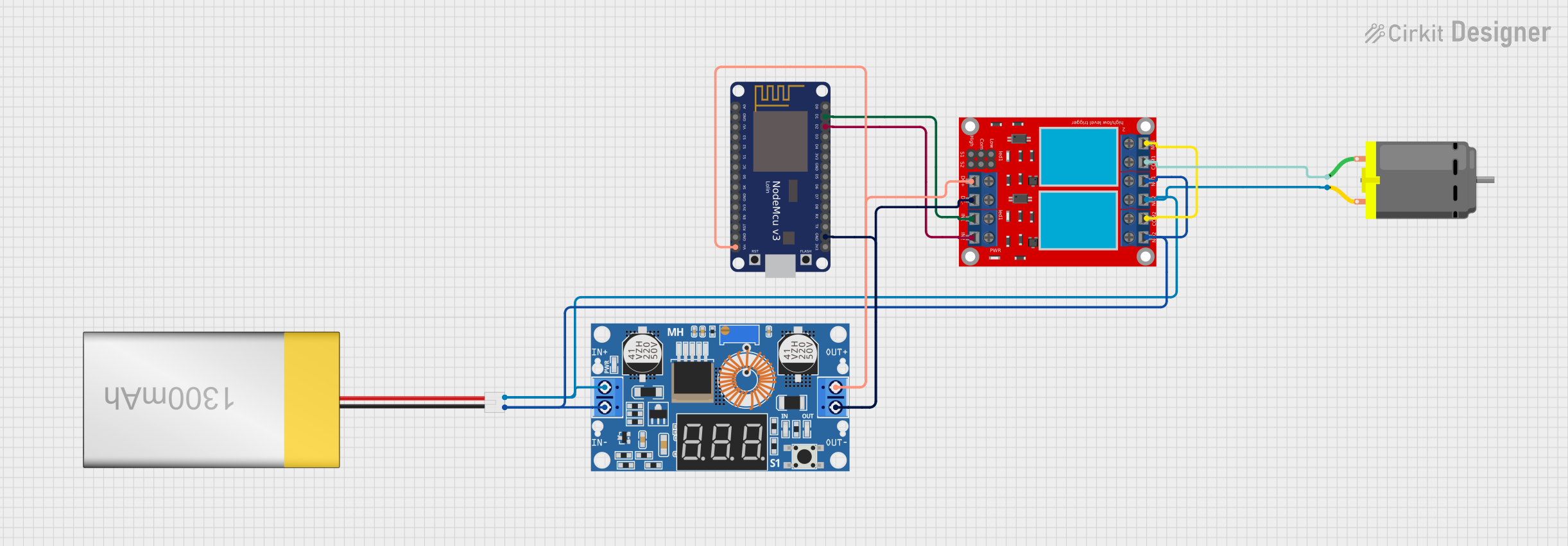
NodeMCU ESP8266 Controlled DC Motor with Relay and Step-down Converter

Circuit Documentation
Summary of the Circuit
This circuit is designed to control a DC motor using a NodeMCU V3 ESP8266 microcontroller and a 2-channel relay module. The power for the circuit is provided by a LiPoly Battery (1300mAh), which is stepped down to a suitable voltage for the NodeMCU and relay module by an XL4015 5A DC Buck Step-down converter. The NodeMCU controls the relay module, which in turn controls the power supplied to the DC motor. The circuit does not include any embedded code as none was provided.
Component List
NodeMCU V3 ESP8266
- A microcontroller board based on the ESP8266 chip, featuring WiFi capability and a variety of digital and analog pins.
LiPoly Battery (1300mAh)
- A lithium polymer battery that provides a power source for the circuit.
2 Channel Relay Module
- A module with two relays that can be used to control high power devices such as motors.
XL4015 5A DC Buck Step-down Converter
- A DC-DC step-down (buck) converter capable of handling up to 5A of current, used to reduce the voltage from the battery to a level suitable for the NodeMCU and relay module.
DC Motor
- A simple DC motor that can be controlled by the relay module to turn on or off.
Wiring Details
NodeMCU V3 ESP8266
Vinconnected to the output voltage of the XL4015 step-down converter.GNDconnected to the ground of the XL4015 step-down converter.D1connected toIN 1on the 2 channel relay module.D2connected toIN 2on the 2 channel relay module.
LiPoly Battery (1300mAh)
positiveconnected toInput +on the XL4015 step-down converter andN.C. 2on the 2 channel relay module.negativeconnected toInput -on the XL4015 step-down converter,N.O. 2, andN.O. 1on the 2 channel relay module.
2 Channel Relay Module
VCC+connected to the output voltage of the XL4015 step-down converter.VCC- (GND)connected to the ground of the XL4015 step-down converter.IN 1controlled byD1on the NodeMCU.IN 2controlled byD2on the NodeMCU.N.O. 1andN.O. 2connected to the negative of the LiPoly Battery.COM 1connected topin 1of the DC Motor.COM 2andN.C. 1are not connected to any other components in the circuit.N.C. 2connected to the positive of the LiPoly Battery andpin 2of the DC Motor.
XL4015 5A DC Buck Step-down Converter
Input +connected to the positive of the LiPoly Battery.Input -connected to the negative of the LiPoly Battery.Output +connected toVCC+on the 2 channel relay module andVinon the NodeMCU.Output -connected toVCC- (GND)on the 2 channel relay module andGNDon the NodeMCU.
DC Motor
pin 1connected toCOM 1on the 2 channel relay module.pin 2connected toN.C. 2on the 2 channel relay module and the positive of the LiPoly Battery.
Documented Code
No code was provided for the microcontroller. If code is later provided, it should be documented here with explanations of how it interacts with the hardware components, including setup, main loop, and any functions or libraries used to control the relay module and, by extension, the DC motor.