
Arduino UNO-Based Automated Water Level Control System with LED Indicator
View and Edit Project In Cirkit Designer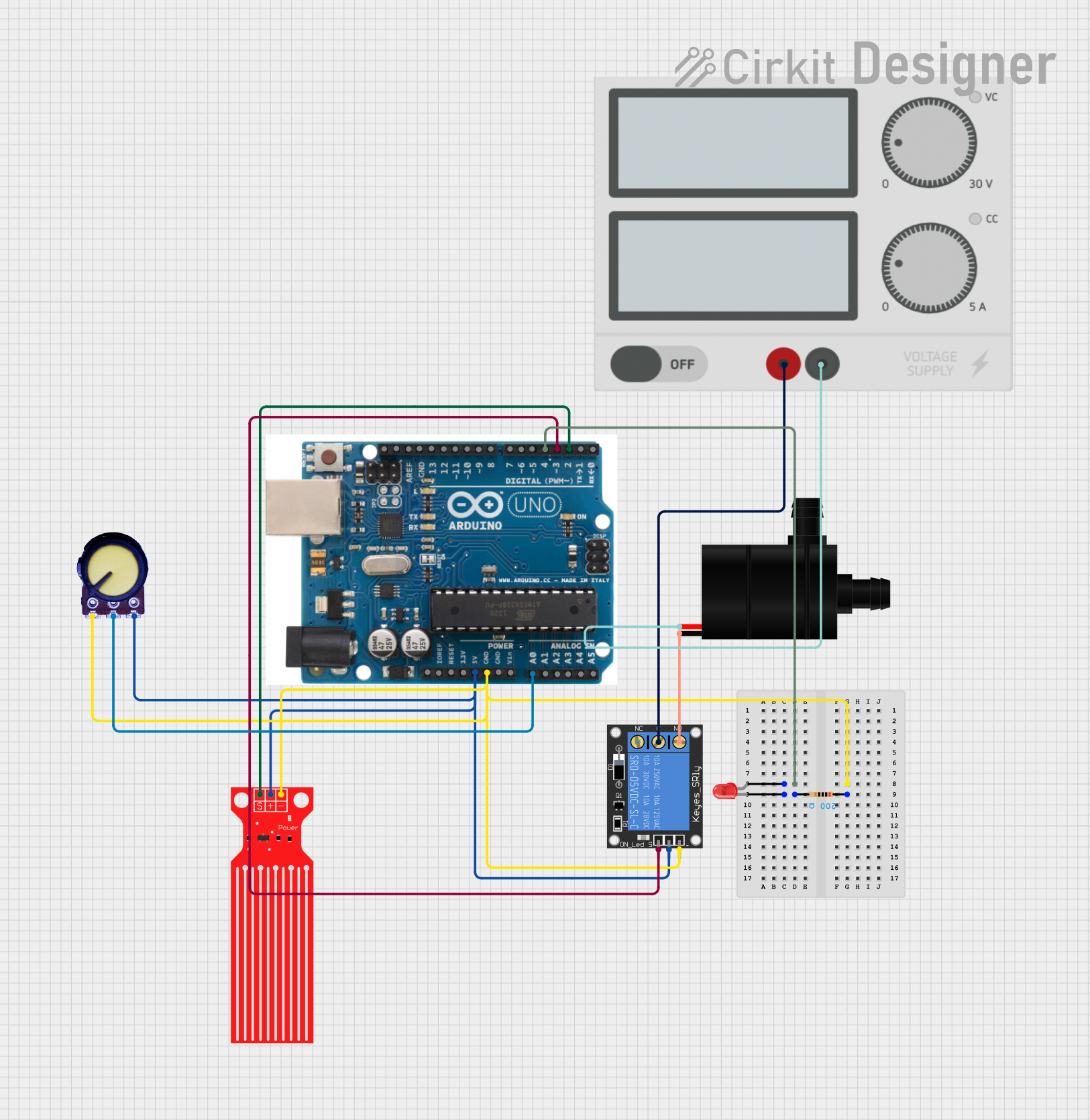
Circuit Documentation
Summary
This circuit is designed to monitor water levels using a water level sensor and control a water pump via a relay. Additionally, it includes a potentiometer for adjustable settings and an LED indicator. The circuit is controlled by an Arduino UNO microcontroller.
Component List
Arduino UNO
- Description: A microcontroller board based on the ATmega328P.
- Pins: SDA, AREF, GND, 13, 12, 11, 10, 9, 8, 7, 6, 5, 4, 3, 2, 1, 0, A5, A4, A3, A2, A1, A0, Vin, 5V, 3.3V, RESET, IOREF, SCL
Water Level Sensor
- Description: A sensor to detect water levels.
- Pins: SIG, VCC, GND
Water Pump
- Description: A pump to move water.
- Pins: VCC, GND
1-Channel Relay (5V 10A)
- Description: A relay module to control high-power devices.
- Pins: NC, signal, C, power, NO, ground
Power Supply
- Description: Provides power to the circuit.
- Pins: +, -
Potentiometer
- Description: A variable resistor for adjustable settings.
- Pins: GND, Output, VCC
LED: Two Pin (red)
- Description: A red LED for visual indication.
- Pins: cathode, anode
Resistor
- Description: A resistor to limit current.
- Pins: pin1, pin2
- Properties: Resistance: 200 Ohms
Wiring Details
Arduino UNO
- Pin 4 connected to LED: Two Pin (red) anode
- Pin 3 connected to 1-Channel Relay (5V 10A) signal
- Pin 2 connected to Water Level Sensor SIG
- Pin A0 connected to Potentiometer Output
- GND connected to 1-Channel Relay (5V 10A) ground, Water Level Sensor GND, Potentiometer GND
- 5V connected to 1-Channel Relay (5V 10A) power, Water Level Sensor VCC, Potentiometer VCC
Water Level Sensor
- SIG connected to Arduino UNO pin 2
- VCC connected to Arduino UNO 5V
- GND connected to Arduino UNO GND
Water Pump
- VCC connected to Power Supply -
- GND connected to 1-Channel Relay (5V 10A) NO
1-Channel Relay (5V 10A)
- signal connected to Arduino UNO pin 3
- ground connected to Arduino UNO GND
- power connected to Arduino UNO 5V
- NO connected to Water Pump GND
- C connected to Power Supply +
Power Supply
- + connected to 1-Channel Relay (5V 10A) C
- - connected to Water Pump VCC
Potentiometer
- Output connected to Arduino UNO pin A0
- GND connected to Arduino UNO GND
- VCC connected to Arduino UNO 5V
LED: Two Pin (red)
- anode connected to Arduino UNO pin 4
- cathode connected to Resistor pin2
Resistor
- pin2 connected to LED: Two Pin (red) cathode
Code Documentation
// Pin definitions
const int potPin = A0;          // Potentiometer connected to analog pin A0
const int waterLevelPin = 2;    // Water level sensor connected to digital pin D2
const int relayPin = 3;         // Relay module connected to digital pin D3
const int ledPin = 4;           // LED connected to digital pin D4

void setup() {
    // Initialize serial communication for debugging
    Serial.begin(9600);

    // Set pin modes
    pinMode(waterLevelPin, INPUT);
    pinMode(relayPin, OUTPUT);
    pinMode(ledPin, OUTPUT);

    // Initial state of relay and LED
    digitalWrite(relayPin, LOW); // Ensure the relay is off initially
    digitalWrite(ledPin, LOW);   // Ensure the LED is off initially
}

void loop() {
    // Read the potentiometer value
    int potValue = analogRead(potPin);

    // Read the water level sensor value
    int waterLevel = digitalRead(waterLevelPin);

    // Print the sensor values to the serial monitor
    Serial.print("Potentiometer Value: ");
    Serial.println(potValue);
    Serial.print("Water Level: ");
    Serial.println(waterLevel);

    // Control the relay and LED based on the water level sensor
    if (waterLevel == HIGH) {
        digitalWrite(relayPin, HIGH);  // Turn on the relay (activate the water pump)
        digitalWrite(ledPin, HIGH);    // Turn on the LED
    } else {
        digitalWrite(relayPin, LOW);   // Turn off the relay (deactivate the water pump)
        digitalWrite(ledPin, LOW);     // Turn off the LED
    }

    // Wait for 1 second before repeating the loop
    delay(1000);
}
This code initializes the pins for the potentiometer, water level sensor, relay, and LED. It reads the values from the potentiometer and water level sensor, prints them to the serial monitor, and controls the relay and LED based on the water level sensor's readings.