
Circuit Documentation
Summary
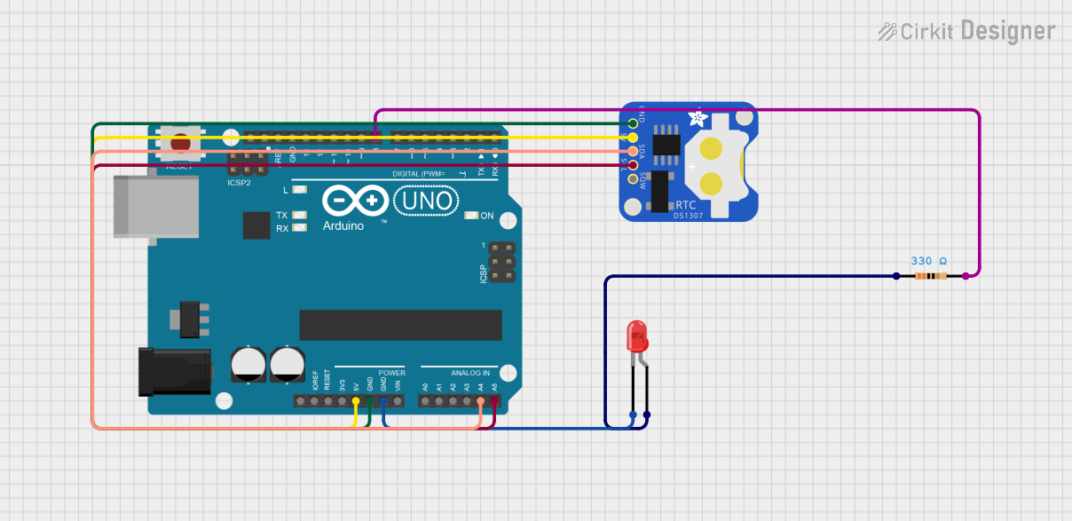
The circuit in question is designed to interface an Arduino UNO with a DS1307 Real-Time Clock (RTC) module and control an LED based on the time provided by the RTC. The LED is connected through a 330-ohm resistor to limit the current. The RTC communicates with the Arduino via the I2C protocol, using the SDA and SCL lines. The LED is controlled by a digital output pin on the Arduino and is turned on or off depending on the time of day.
Component List
Arduino UNO
- Description: A microcontroller board based on the ATmega328P.
- Purpose: Acts as the central controller for the circuit, running the embedded code to interact with the RTC and control the LED.
DS1307 RTC (Wokwi Compatible)
- Description: A real-time clock module for keeping track of the current time.
- Purpose: Provides accurate time information to the Arduino.
LED: Two Pin (red)
- Description: A basic red light-emitting diode.
- Purpose: Serves as an indicator that is controlled by the Arduino based on the RTC's time.
Resistor
- Description: A passive two-terminal electrical component with a resistance of 330 Ohms.
- Purpose: Limits the current flowing through the LED to prevent damage.
Wiring Details
Arduino UNO
- 5V connected to DS1307 RTC 5V.
- GND connected to DS1307 RTC GND and LED cathode.
- A4 (SDA) connected to DS1307 RTC SDA.
- A5 (SCL) connected to DS1307 RTC SCL.
- D8 connected to one end of the Resistor.
DS1307 RTC (Wokwi Compatible)
- 5V connected to Arduino UNO 5V.
- GND connected to Arduino UNO GND.
- SDA connected to Arduino UNO A4.
- SCL connected to Arduino UNO A5.
LED: Two Pin (red)
- Cathode connected to Arduino UNO GND.
- Anode connected to one end of the Resistor.
Resistor
- Pin1 connected to LED anode.
- Pin2 connected to Arduino UNO D8.
Documented Code
#include <Wire.h>
#include <RTClib.h>  // Ensure this is the RTCLib by NeiroN

RTC_DS1307 rtc;

const int lightPin = 8;  // Pin connected to the LED or relay

void setup() {
  Serial.begin(9600);
  if (!rtc.begin()) {
    Serial.println("Couldn't find RTC");
    while (1);
  }

  if (!rtc.isrunning()) {
    Serial.println("RTC is NOT running, setting the time...");
    // Uncomment the following line to set the RTC to the time the sketch was compiled
    rtc.adjust(DateTime(F(__DATE__), F(__TIME__)));
  }

  pinMode(lightPin, OUTPUT);
  digitalWrite(lightPin, LOW);  // Start with light off
}

void loop() {
  DateTime now = rtc.now();

  int currentHour = now.hour();
  int currentMinute = now.minute();

  // Check if the current time is between 11:00 AM and 11:43 AM
  if ((currentHour == 11) && (currentMinute >= 0 && currentMinute <= 43)) {
    digitalWrite(lightPin, HIGH);  // Turn on the light
    Serial.println("Light ON");
  } else {
    digitalWrite(lightPin, LOW);   // Turn off the light
    Serial.println("Light OFF");
  }

  delay(1000);  // Check every second
}
Filename: sketch.ino
Description: This code initializes the RTC and sets the current time if the RTC is not running. It then enters a loop where it checks the current time and turns on an LED connected to pin D8 of the Arduino if the time is between 11:00 AM and 11:43 AM. The LED is turned off outside of this time window. The status of the LED is printed to the serial monitor every second.