
Arduino UNO Self-Balancing Robot with MPU6050 and L298N Motor Driver
View and Edit Project In Cirkit Designer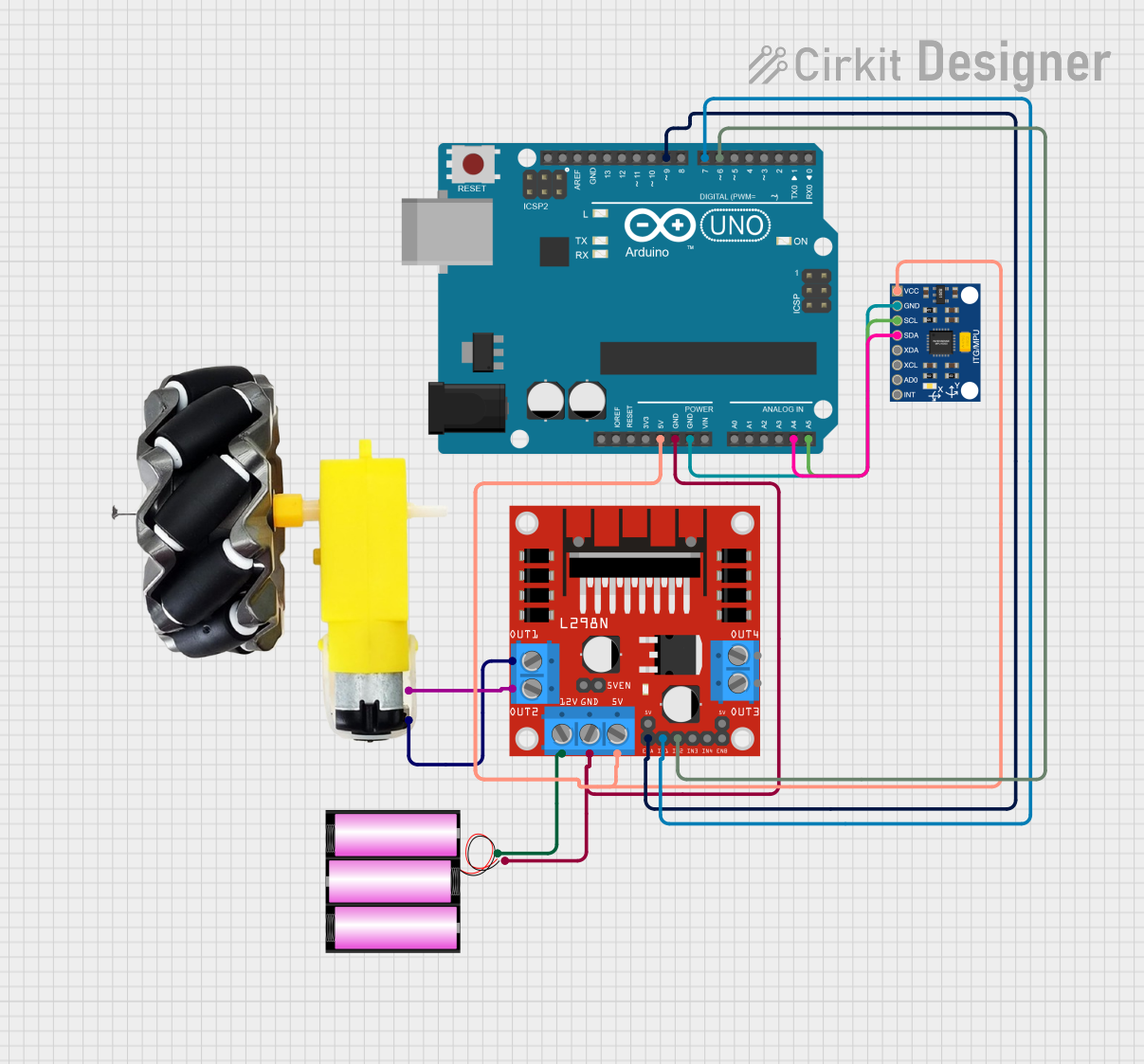
Circuit Documentation
Summary
This circuit is designed to control a motor and wheels system using an Arduino UNO microcontroller, an L298N DC motor driver, and an MPU6050 sensor for motion detection. The system is powered by a 12V battery. The Arduino UNO reads data from the MPU6050 sensor and uses a PID controller to adjust the motor speed and direction to maintain a setpoint angle.
Component List
Arduino UNO
- Description: Microcontroller board based on the ATmega328P.
- Pins: UNUSED, IOREF, Reset, 3.3V, 5V, GND, Vin, A0, A1, A2, A3, A4, A5, SCL, SDA, AREF, D13, D12, D11, D10, D9, D8, D7, D6, D5, D4, D3, D2, D1, D0
Motor and Wheels
- Description: Motor and wheels system for movement.
- Pins: vcc, GND
L298N DC Motor Driver
- Description: Dual H-Bridge motor driver for controlling DC motors.
- Pins: OUT1, OUT2, 12V, GND, 5V, OUT3, OUT4, 5V-ENA-JMP-I, 5V-ENA-JMP-O, +5V-J1, +5V-J2, ENA, IN1, IN2, IN3, IN4, ENB
Battery 12V
- Description: 12V battery for powering the circuit.
- Pins: +, -
InvenSense MPU6050
- Description: 6-axis motion tracking device.
- Pins: VCC, GND, SCL, SDA, XDA, XCL, AD0, INT
Wiring Details
Arduino UNO
5V connected to:
- L298N DC Motor Driver (5V)
- InvenSense MPU6050 (VCC)
GND connected to:
- L298N DC Motor Driver (GND)
- InvenSense MPU6050 (GND)
- Battery 12V (-)
A4 connected to:
- InvenSense MPU6050 (SDA)
A5 connected to:
- InvenSense MPU6050 (SCL)
D9 connected to:
- L298N DC Motor Driver (ENA)
D7 connected to:
- L298N DC Motor Driver (IN1)
D6 connected to:
- L298N DC Motor Driver (IN2)
Motor and Wheels
vcc connected to:
- L298N DC Motor Driver (OUT1)
GND connected to:
- L298N DC Motor Driver (OUT2)
L298N DC Motor Driver
5V connected to:
- Arduino UNO (5V)
- InvenSense MPU6050 (VCC)
GND connected to:
- Arduino UNO (GND)
- Battery 12V (-)
ENA connected to:
- Arduino UNO (D9)
IN1 connected to:
- Arduino UNO (D7)
IN2 connected to:
- Arduino UNO (D6)
OUT1 connected to:
- Motor and Wheels (vcc)
OUT2 connected to:
- Motor and Wheels (GND)
12V connected to:
- Battery 12V (+)
Battery 12V
+ connected to:
- L298N DC Motor Driver (12V)
- connected to:
- Arduino UNO (GND)
- L298N DC Motor Driver (GND)
InvenSense MPU6050
VCC connected to:
- Arduino UNO (5V)
- L298N DC Motor Driver (5V)
GND connected to:
- Arduino UNO (GND)
SDA connected to:
- Arduino UNO (A4)
SCL connected to:
- Arduino UNO (A5)
Code Documentation
#include <PID_v1.h>
#include <Wire.h>
#include "I2Cdev.h"
#include "MPU6050_6Axis_MotionApps20.h"

// Motor pins for L298N (controlling one motor)
int ENA = 9;
int IN1 = 7;
int IN2 = 6;

#define MIN_ABS_SPEED 35  // Increased minimum speed for better response

// MPU6050 object
MPU6050 mpu;

// MPU control/status vars
bool dmpReady = false;
uint8_t mpuIntStatus;
uint8_t devStatus;
uint16_t packetSize;
uint16_t fifoCount;
uint8_t fifoBuffer[64];

// Orientation/motion vars
Quaternion q;
VectorFloat gravity;
float ypr[3];

// PID parameters
double setpoint = -5.5; // Target angle (upright, adjusted for 0 degrees)
double input, output;
double Kp = 30.0;   // Stronger corrective force for larger pendulum
double Kd = 0.5;    // Increased to help stabilize oscillations
double Ki = 200.0;  // Adjusted to prevent oscillations over time
PID pid(&input, &output, &setpoint, Kp, Ki, Kd, DIRECT);

// Motor control function for one motor
void setMotorSpeed(int speed) {
    // Ensure speed is within -255 to 255
    speed = constrain(speed, -255, 255);

    // Apply minimum speed for movement if needed
    if (speed > 0) {
        speed = max(speed, MIN_ABS_SPEED);
    } else if (speed < 0) {
        speed = min(speed, -MIN_ABS_SPEED);
    }

    if (speed > 0) {
        // Move forward
        analogWrite(ENA, speed);
        digitalWrite(IN1, HIGH);
        digitalWrite(IN2, LOW);
    } else if (speed < 0) {
        // Move backward
        analogWrite(ENA, -speed);
        digitalWrite(IN1, LOW);
        digitalWrite(IN2, HIGH);
    } else {
        // Stop motor
        analogWrite(ENA, 0);
    }
}

volatile bool mpuInterrupt = false;
void dmpDataReady() {
    mpuInterrupt = true;
}

void setup() {
    Serial.begin(2000000);

    // Motor pins setup
    pinMode(ENA, OUTPUT);
    pinMode(IN1, OUTPUT);
    pinMode(IN2, OUTPUT);

    // Wire setup for MPU6050
    Wire.begin();
    TWBR = 24; // Set I2C speed to 400kHz

    // MPU6050 initialization
    mpu.initialize();
    devStatus = mpu.dmpInitialize();

    // Supply your own gyro offsets here, scaled for min sensitivity
    mpu.setXGyroOffset(0);
    mpu.setYGyroOffset(0);
    mpu.setZGyroOffset(0);
    mpu.setZAccelOffset(0); // Adjust based on your calibration

    if (devStatus == 0) {
        mpu.setDMPEnabled(true);
        attachInterrupt(digitalPinToInterrupt(2), dmpDataReady, RISING);
        mpuIntStatus = mpu.getIntStatus();
        dmpReady = true;
        packetSize = mpu.dmpGetFIFOPacketSize();

        // PID setup
        pid.SetMode(AUTOMATIC);
        pid.SetSampleTime(10);
        pid.SetOutputLimits(-255, 255);
    } else {
        Serial.print(F("DMP Initialization failed (code "));
        Serial.print(devStatus);
        Serial.println(F(")"));
    }
}

void loop() {
    if (!dmpReady) return;

    // Wait for MPU interrupt or extra packet(s) available
    while (!mpuInterrupt && fifoCount < packetSize) {
        // No new MPU data, run PID calculations
        pid.Compute();
        setMotorSpeed(output);

        // Print data for visualization
        Serial.print("Setpoint: ");
        Serial.print(setpoint);
        Serial.print(" | Input: ");
        Serial.print(input);
        Serial.print(" | Output: ");
        Serial.println(output);
    }

    mpuInterrupt = false;
    mpuIntStatus = mpu.getIntStatus();
    fifoCount = mpu.getFIFOCount();

    if ((mpuIntStatus & 0x10) || fifoCount == 1024) {
        mpu.resetFIFO();
        Serial.println(F("FIFO overflow!"));
    } else if (mpuIntStatus & 0x02) {
        while (fifoCount < packetSize) fifoCount = mpu.getFIFOCount();

        mpu.getFIFOBytes(fifoBuffer, packetSize);
        fifoCount -= packetSize;

        mpu.dmpGetQuaternion(&q, fifoBuffer);
        mpu.dmpGetGravity(&gravity, &q);
        mpu.dmpGetYawPitchRoll(ypr, &q, &