
ESP32-Based Health Monitoring and Control System with MAX30102, Load Cell, and TFT Display
View and Edit Project In Cirkit Designer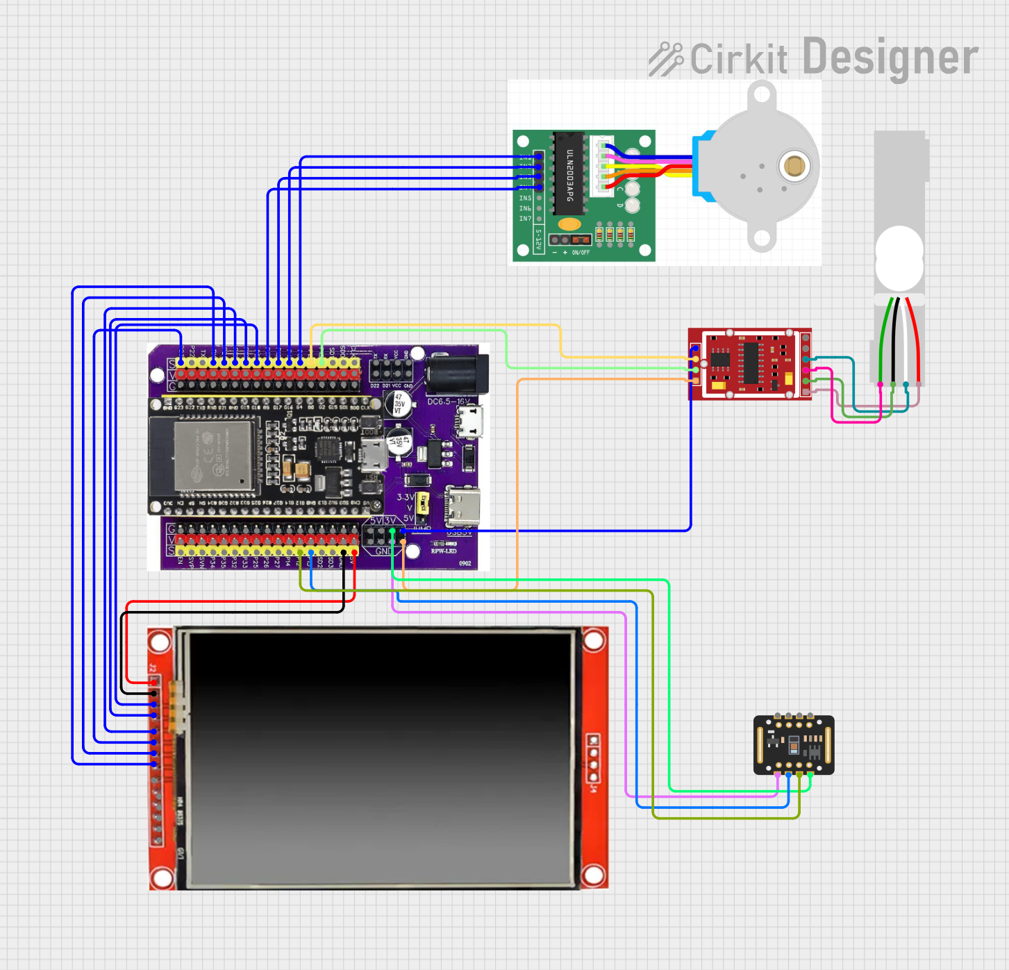
Circuit Documentation
Summary
This document provides a detailed overview of a circuit that includes various components such as a MAX30102 sensor, an LCD TFT screen, a load cell, an ESP32 microcontroller, a stepper motor, and an HX711 weighing sensor module. The document includes a component list, wiring details, and code documentation.
Component List
MAX30102
- Description: A pulse oximeter and heart-rate sensor.
- Pins: VIN, SDA, SCL, GND, RD, IRD, INT
- Purpose in Circuit: Measures heart rate and blood oxygen levels.
LCD TFT screen ILI9488 HD
- Description: A high-definition LCD screen with touch capabilities.
- Pins: PEN, TDO, TDI, VCC (3.3~5V), GND, CS, RST, D/C, SDI(MOSI), SCK, BL, SDO(MISO), TCS, TCK
- Purpose in Circuit: Displays information and provides a user interface.
Load Cell - Red/white/black/green
- Description: A sensor used to measure weight.
- Pins: E+, A-, E-, A+
- Purpose in Circuit: Measures weight for various applications.
ESP32 on Baseboard
- Description: A microcontroller with Wi-Fi and Bluetooth capabilities.
- Pins: GPIO23, GPIO22, GPIO1/TX, GPIO3/RX, GPIO21, GPIO19, GPIO18, GPIO5, GPIO17, GPIO16, GPIO4, GPIO0, GPIO2, GPIO15, SD1, SD0, CLK, V, G, GPIO36, GPIO39, GPIO34, GPIO35, GPIO32, GPIO33, GPIO25, GPIO26, GPIO27, GPIO14, GPIO12, GPIO13, SD2, SD3, GND, 5V, 3V, TX, RX, VCC, D22, D21
- Purpose in Circuit: Acts as the main controller for the circuit, handling data processing and communication.
Stepper Motor One
- Description: A motor that moves in discrete steps, used for precise control.
- Pins: IN1, IN2, IN3, IN4, +, -
- Purpose in Circuit: Provides precise movement for mechanical components.
HX711 Weighing Sensor Module
- Description: A precision 24-bit analog-to-digital converter (ADC) designed for weigh scales.
- Pins: B-, B+, A-, A+, E-, E+, VCC, CK/TX, DO/RX, GND
- Purpose in Circuit: Converts the analog signal from the load cell to a digital signal for the microcontroller.
Wiring Details
MAX30102
- VIN: Connected to ESP32 pin 3V
- SDA: Connected to ESP32 pin GPIO12
- SCL: Connected to ESP32 pin GPIO13
- GND: Connected to ESP32 pin GND
LCD TFT screen ILI9488 HD
- VCC (3.3~5V): Connected to ESP32 pin 5V
- GND: Connected to ESP32 pin GND
- CS: Connected to ESP32 pin GPIO5
- RST: Connected to ESP32 pin GPIO18
- D/C: Connected to ESP32 pin GPIO19
- SDI(MOSI): Connected to ESP32 pin GPIO23
- SCK: Connected to ESP32 pin GPIO21
- BL: Connected to ESP32 pin GPIO3/RX
Load Cell - Red/white/black/green
- E+: Connected to HX711 pin E+
- A-: Connected to HX711 pin A-
- E-: Connected to HX711 pin E-
- A+: Connected to HX711 pin A+
ESP32 on Baseboard
- 3V: Connected to MAX30102 pin VIN, HX711 pin VCC
- GPIO12: Connected to MAX30102 pin SDA
- GPIO13: Connected to MAX30102 pin SCL
- GND: Connected to MAX30102 pin GND, HX711 pin GND, LCD TFT screen pin GND
- 5V: Connected to LCD TFT screen pin VCC (3.3~5V)
- GPIO5: Connected to LCD TFT screen pin CS
- GPIO18: Connected to LCD TFT screen pin RST
- GPIO19: Connected to LCD TFT screen pin D/C
- GPIO23: Connected to LCD TFT screen pin SDI(MOSI)
- GPIO21: Connected to LCD TFT screen pin SCK
- GPIO3/RX: Connected to LCD TFT screen pin BL
- GPIO17: Connected to Stepper Motor pin IN4
- GPIO16: Connected to Stepper Motor pin IN3
- GPIO4: Connected to Stepper Motor pin IN2
- GPIO0: Connected to Stepper Motor pin IN1
- GPIO2: Connected to HX711 pin CK/TX
- GPIO15: Connected to HX711 pin DO/RX
Stepper Motor One
- IN4: Connected to ESP32 pin GPIO17
- IN3: Connected to ESP32 pin GPIO16
- IN2: Connected to ESP32 pin GPIO4
- IN1: Connected to ESP32 pin GPIO0
HX711 Weighing Sensor Module
- E+: Connected to Load Cell pin E+
- A-: Connected to Load Cell pin A-
- E-: Connected to Load Cell pin E-
- A+: Connected to Load Cell pin A+
- VCC: Connected to ESP32 pin 3V
- CK/TX: Connected to ESP32 pin GPIO2
- DO/RX: Connected to ESP32 pin GPIO15
- GND: Connected to ESP32 pin GND
Code Documentation
No code is provided for this circuit.
This document provides a comprehensive overview of the circuit, including the components used, their connections, and their purposes. This should serve as a useful reference for understanding and troubleshooting the circuit.