
ESP8266 NodeMCU-Based Water Level Monitoring System with Wi-Fi Connectivity
View and Edit Project In Cirkit Designer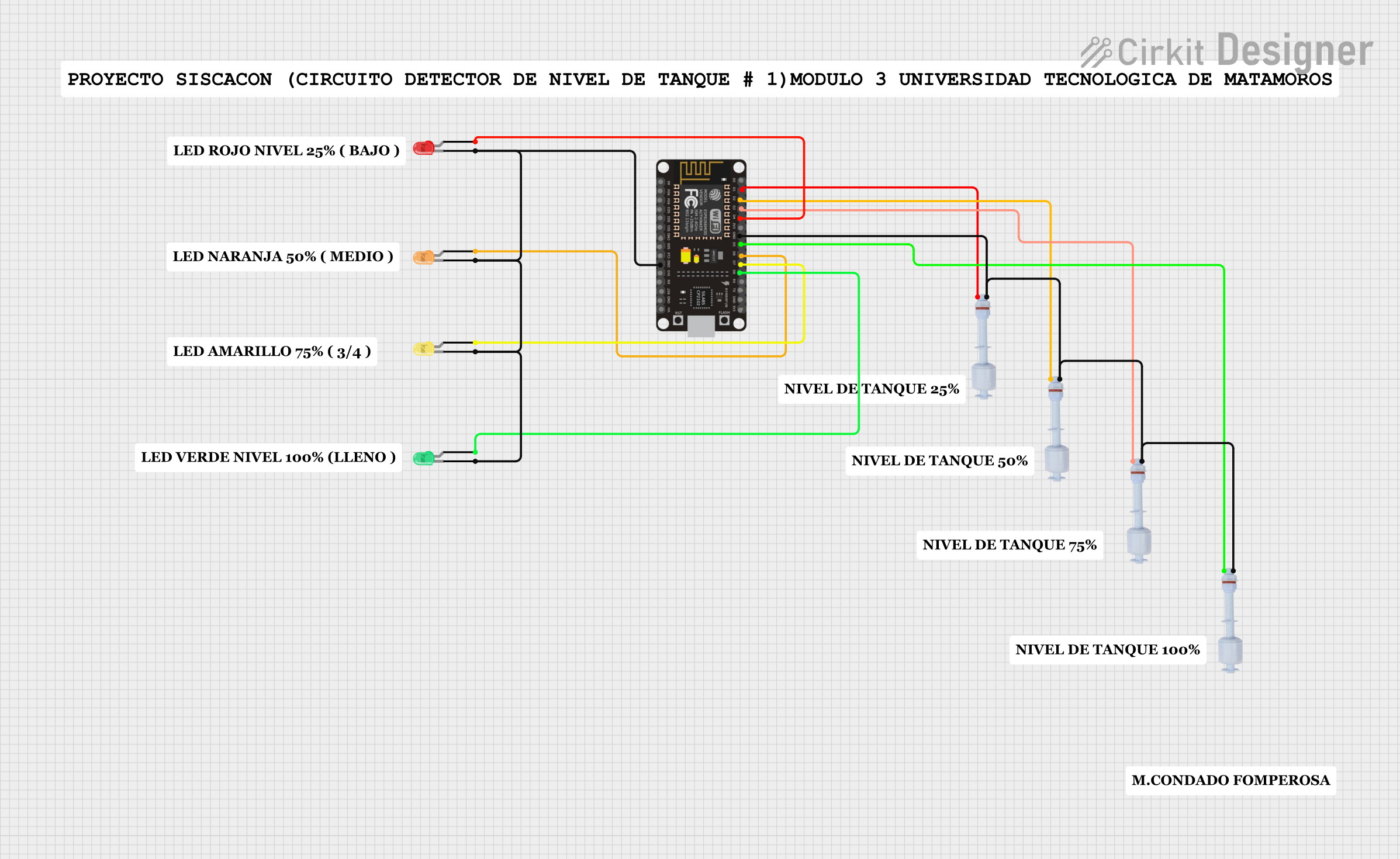
Circuit Documentation
Summary
The circuit in question appears to be designed for monitoring liquid levels using multiple float switches and providing visual feedback through a series of LEDs. The core of the circuit is an ESP8266 NodeMCU microcontroller, which is responsible for reading the states of the float switches and controlling the LEDs accordingly. The microcontroller also has capabilities for connecting to WiFi networks and sending data to a ThingSpeak channel, which suggests that this circuit may be part of an IoT application for remote monitoring.
Component List
- ESP8266 NodeMCU: A microcontroller with WiFi capabilities, used as the central processing unit of the circuit.
- Float Switches (4x): Sensors used to detect the level of liquid within a container.
- LED (Red): A visual indicator that can be used to represent a specific state of the liquid level.
- LED (Green): Another visual indicator for representing a different state of the liquid level.
- LED (Yellow): An additional visual indicator for liquid level states.
- LED (Orange): A visual indicator for yet another state of the liquid level.
- Comments: These are placeholders or annotations within the circuit design and do not represent physical components.
Wiring Details
ESP8266 NodeMCU
- D1: Connected to the digital pin of the first float switch.
- D2: Connected to the digital pin of the second float switch.
- D3: Connected to the digital pin of the third float switch.
- D4: Connected to the anode of the red LED.
- D5: Connected to the digital pin of the fourth float switch.
- D6: Connected to the anode of the orange LED.
- D7: Connected to the anode of the yellow LED.
- D8: Connected to the anode of the green LED.
- GND: Common ground connected to the ground pins of all float switches and the cathodes of all LEDs.
Float Switches
- Digital Pin: Each float switch has its digital pin connected to a corresponding GPIO on the ESP8266 NodeMCU.
- GND: All float switches share a common ground connection with the ESP8266 NodeMCU.
LEDs
- Anode (Red, Green, Yellow, Orange): Each LED's anode is connected to a specific GPIO on the ESP8266 NodeMCU.
- Cathode (Red, Green, Yellow, Orange): All LEDs share a common ground connection with the ESP8266 NodeMCU.
Documented Code
The code provided is intended for the ESP8266 NodeMCU microcontroller. It includes functionality for reading the state of the float switches, controlling the LEDs, connecting to WiFi networks, and sending data to a ThingSpeak channel.
#include <ESP8266WiFiMulti.h>

ESP8266WiFiMulti wifiMulti;
// WiFi connect timeout per AP. Increase when connecting takes longer.
const uint32_t connectTimeoutMs = 5000;
#include "ThingSpeak.h"

bool Estado1 = false;
bool Estado2 = false;
bool Estado3 = false;
bool Estado4 = false;
int Pin1 = D1;
int Pin2 = D2;
int Pin3 = D3;
int Pin5 = D5;
// LED GPIO assignments
int led1 = 2; // D4 - Red LED
int led2 = 12; // D6 - Orange LED
int led3 = 13; // D7 - Yellow LED
int led4 = 15; // D8 - Green LED

unsigned long ch_no = 918427; // Replace with ThingSpeak Channel number
const char *write_api = "39Z5LSRN8M1EPDPQ"; // Replace with ThingSpeak write API
char auth[] = "mi710807";
char ssid[] = "WIFI DOCENTES";
char pass[] = "UTMmatamoros201809";
unsigned long startMillis;
unsigned long currentMillis;
const unsigned long period = 25000;
WiFiClient client;

void setup() {
  pinMode(led1, OUTPUT); // Red LED
  pinMode(led2, OUTPUT); // Orange LED
  pinMode(led3, OUTPUT); // Yellow LED
  pinMode(led4, OUTPUT); // Green LED

  pinMode(Pin1, INPUT_PULLUP);
  pinMode(Pin2, INPUT_PULLUP);
  pinMode(Pin3, INPUT_PULLUP);
  pinMode(Pin5, INPUT_PULLUP);
  // Don't save WiFi configuration in flash - optional
  WiFi.persistent(false);

  Serial.begin(115200);
  Serial.println("\nESP8266 Multi WiFi");
  WiFi.mode(WIFI_STA);
  // Register multi WiFi networks
  wifiMulti.addAP("ESP32.2", "KONAN123");
  wifiMulti.addAP("ESP32.3", "KONAN123");
  wifiMulti.addAP("SM-A505U02B", "deraj2000");
  // Maintain WiFi connection
  if (wifiMulti.run(connectTimeoutMs) == WL_CONNECTED) {
    Serial.println("WiFi connected: ");
    delay(2000);
    Serial.println(WiFi.SSID());
    delay(4000);
    Serial.print(" ");
    delay(4000);
    Serial.println(WiFi.localIP());
    delay(2000);
  } else {
    Serial.println("WiFi not connected!");
  }
  ThingSpeak.begin(client);
  startMillis = millis(); // Initial start time
}

void loop() {
  Estado1 = digitalRead(Pin1);
  Estado2 = digitalRead(Pin2);
  Estado3 = digitalRead(Pin3);
  Estado4 = digitalRead(Pin5);
  // Logic for LED control based on float switch states
  // and ThingSpeak updates
  // ...
  // Rest of the code handling the LED states and ThingSpeak communication
  // ...
}
The code above is a simplified representation of the actual code provided. It includes the setup of GPIO pins, WiFi connection handling, and the main loop that reads the float switch states and controls the LEDs. The comments within the code indicate where additional logic for LED control and ThingSpeak communication is implemented.