
Arduino Mega 2560 Smart Sensor Hub with LoRa and Camera Integration
View and Edit Project In Cirkit Designer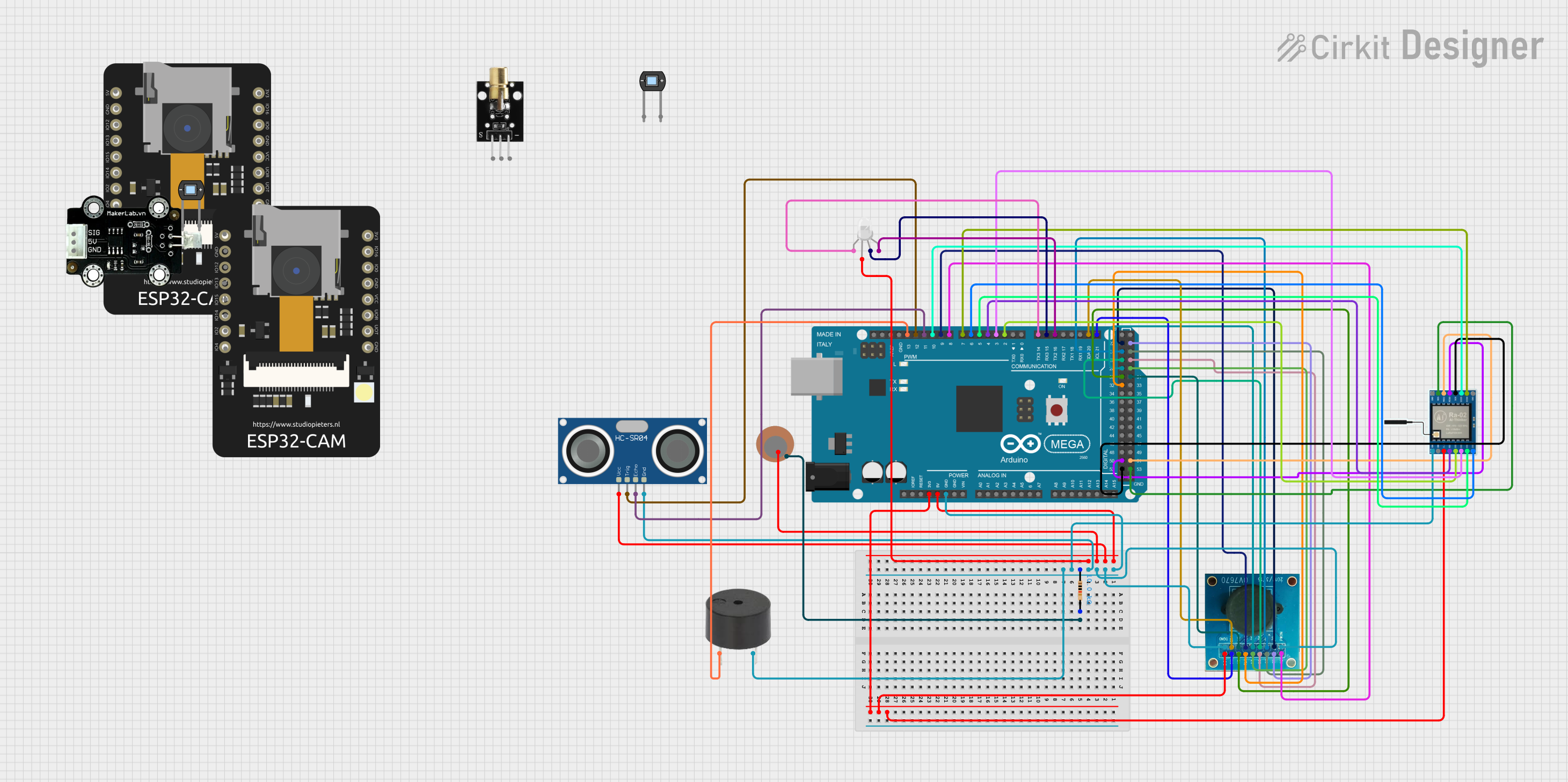
Circuit Documentation
Summary
This document provides a detailed overview of a circuit that includes various sensors, an RGB LED, a buzzer, a LoRa module, and two microcontrollers (Arduino Mega 2560 and ESP32 CAM). The circuit is designed to interface these components for various sensing and communication tasks.
Component List
Resistor
- Description: A resistor with a resistance of 10k Ohms.
- Pins: pin1, pin2
HC-SR04 Ultrasonic Sensor
- Description: An ultrasonic sensor used for distance measurement.
- Pins: VCC, TRIG, ECHO, GND
Piezo Sensor
- Description: A piezoelectric sensor used for detecting vibrations.
- Pins: +, -
OV7670
- Description: A camera module used for capturing images.
- Pins: RET, PWDN, D1, D0, D3, D2, D4, D5, D6, PLK, XLK, D7, VS, HS, SCL, SDA, 3.3V, DGND
RGB LED (Wokwi compatible)
- Description: An RGB LED used for displaying different colors.
- Pins: R, COM, G, B
Buzzer
- Description: A buzzer used for sound output.
- Pins: PIN, GND
LoRa Ra-02 SX1278
- Description: A LoRa module used for long-range communication.
- Pins: GND, NSS, MOSI, MISO, SCK, D105, DI04, 3.3V, RST, DI00, DI01, D102, DI03
Arduino Mega 2560
- Description: A microcontroller used for controlling the circuit.
- Pins: IOREF, RESET, 3V3, 5V, GND, VIN, A0, A1, A2, A3, A4, A5, A6, A7, A8, A9, A10, A11, A12, A13, A14, A15, D21/SCL, D20/SDA, D19/RX1, D18/TX1, D17 PWM/RX2, D16 PWM/TX2, D15/RX3, D14/TX3, D0 RX0, D1 TX0, D2 PWM, D3 PWM, D4 PWM, D5 PWM, D6 PWM, D7 PWM, D8 PWM, D9 PWM, D10 PWM, D11 PWM, D12 PWM, D13 PWM, AREF, SDA, SCL, D52, D50, D48, D46, D44, D42, D40, D38, D36, D34, D32, D30, D28, D26, D24, D22, D53, D51, D49, D47, D45, D43, D41, D39, D37, D35, D33, D31, D29, D27, D25, D23, 6swdw
ESP32 CAM
- Description: A microcontroller with a built-in camera used for capturing images and video.
- Pins: 5V, GND, GPIO12, GPIO13, GPIO15, GPIO14, GPIO2, GPIO4, 3.3V, GPIO16, GPIO0, 3.3V / 5V / P_OUT, GPIO3 / RX, GPIO1 / TX
Photodiode
- Description: A photodiode used for detecting light.
- Pins: cathode, anode
MKE-S03 Photo Diode Light Sensor
- Description: A light sensor used for detecting light intensity.
- Pins: SIG, 5V, GND
KY-008 Laser Emitter
- Description: A laser emitter used for emitting a laser beam.
- Pins: SIG, 5v, GND
Wiring Details
Resistor
- pin1: Connected to GND of Arduino Mega 2560
- pin2: Connected to - of Piezo Sensor
HC-SR04 Ultrasonic Sensor
- VCC: Connected to 5V of Arduino Mega 2560
- TRIG: Connected to D12 PWM of Arduino Mega 2560
- ECHO: Connected to D11 PWM of Arduino Mega 2560
- GND: Connected to GND of Arduino Mega 2560
Piezo Sensor
- +: Connected to 5V of Arduino Mega 2560
- -: Connected to pin2 of Resistor
OV7670
- RET: Connected to D8 PWM of Arduino Mega 2560
- PWDN: Connected to GND of Arduino Mega 2560
- D1: Connected to D23 of Arduino Mega 2560
- D0: Connected to D22 of Arduino Mega 2560
- D3: Connected to D25 of Arduino Mega 2560
- D2: Connected to D24 of Arduino Mega 2560
- D4: Connected to D26 of Arduino Mega 2560
- D5: Connected to D27 of Arduino Mega 2560
- D6: Connected to D28 of Arduino Mega 2560
- PLK: Connected to D32 of Arduino Mega 2560
- XLK: Connected to D9 PWM of Arduino Mega 2560
- D7: Connected to D29 of Arduino Mega 2560
- VS: Connected to D30 of Arduino Mega 2560
- HS: Connected to D31 of Arduino Mega 2560
- SCL: Connected to D21/SCL of Arduino Mega 2560
- SDA: Connected to D20/SDA of Arduino Mega 2560
- 3.3V: Connected to 3V3 of Arduino Mega 2560
- DGND: Connected to GND of Arduino Mega 2560
RGB LED (Wokwi compatible)
- R: Connected to D14/TX3 of Arduino Mega 2560
- COM: Connected to 5V of Arduino Mega 2560
- G: Connected to D15/RX3 of Arduino Mega 2560
- B: Connected to D16 PWM/TX2 of Arduino Mega 2560
Buzzer
- PIN: Connected to D13 PWM of Arduino Mega 2560
- GND: Connected to GND of Arduino Mega 2560
LoRa Ra-02 SX1278
- GND: Connected to GND of Arduino Mega 2560
- NSS: Connected to D53 of Arduino Mega 2560
- MOSI: Connected to D51 of Arduino Mega 2560
- MISO: Connected to D50 of Arduino Mega 2560
- SCK: Connected to D52 of Arduino Mega 2560
- D105: Connected to D10 PWM of Arduino Mega 2560
- DI04: Connected to D7 PWM of Arduino Mega 2560
- 3.3V: Connected to 3V3 of Arduino Mega 2560
- RST: Connected to D4 PWM of Arduino Mega 2560
- DI00: Connected to D2 PWM of Arduino Mega 2560
- DI01: Connected to D3 PWM of Arduino Mega 2560
- D102: Connected to D5 PWM of Arduino Mega 2560
- DI03: Connected to D6 PWM of Arduino Mega 2560
Arduino Mega 2560
- 5V: Connected to VCC of HC-SR04 Ultrasonic Sensor, + of Piezo Sensor, COM of RGB LED (Wokwi compatible)
- GND: Connected to pin1 of Resistor, DGND and PWDN of OV7670, GND of HC-SR04 Ultrasonic Sensor, GND of LoRa Ra-02 SX1278, GND of Buzzer
- 3V3: Connected to 3.3V of OV7670, 3.3V of LoRa Ra-02 SX1278
ESP32 CAM
- No connections specified in the provided net list
Photodiode
- No connections specified in the provided net list
MKE-S03 Photo Diode Light Sensor
- No connections specified in the provided net list
KY-008 Laser Emitter
- No connections specified in the provided net list
Documented Code
Arduino Mega 2560 Code (sketch.ino)
void setup() {
  // put your setup code here, to run once:

}

void loop() {
  // put your main code here, to run repeatedly:

}
Additional Documentation (documentation.txt)
This document provides a comprehensive overview of the circuit, including a summary, component list, wiring details, and documented code.