
Arduino UNO-Based Multi-Servo Control System with Potentiometer Inputs
View and Edit Project In Cirkit Designer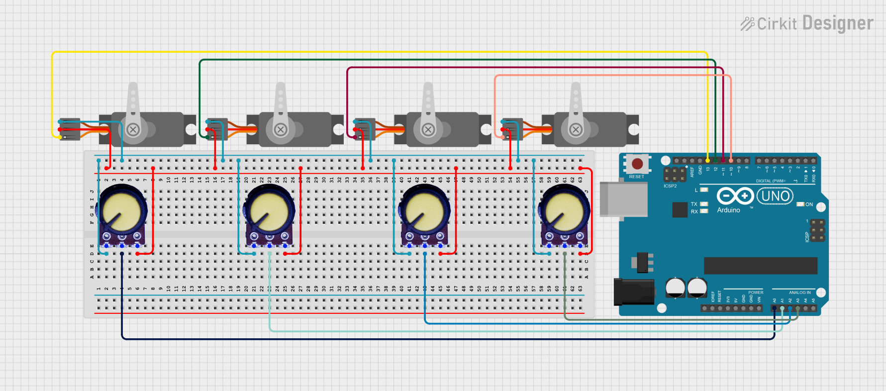
Circuit Documentation
Summary
This circuit consists of an Arduino UNO microcontroller, four potentiometers, and four servo motors. The potentiometers are used to provide analog input to the Arduino, which then controls the servo motors based on the input values.
Component List
Arduino UNO
- Description: A microcontroller board based on the ATmega328P.
- Pins: UNUSED, IOREF, Reset, 3.3V, 5V, GND, Vin, A0, A1, A2, A3, A4, A5, SCL, SDA, AREF, D13, D12, D11, D10, D9, D8, D7, D6, D5, D4, D3, D2, D1, D0
Servo (Wokwi Compatible)
- Description: A servo motor compatible with Wokwi.
- Pins: GND, V+, PWM
Potentiometer
- Description: A variable resistor used to provide analog input.
- Pins: GND, Output, VCC
Wiring Details
Arduino UNO
- A0: Connected to the Output pin of Potentiometer 1
- A1: Connected to the Output pin of Potentiometer 2
- A2: Connected to the Output pin of Potentiometer 3
- A3: Connected to the Output pin of Potentiometer 4
- D10: Connected to the PWM pin of Servo 1
- D11: Connected to the PWM pin of Servo 2
- D12: Connected to the PWM pin of Servo 3
- D13: Connected to the PWM pin of Servo 4
Servo 1 (Wokwi Compatible)
- GND: Connected to the GND pin of Potentiometer 1
- V+: Connected to the VCC pin of Potentiometer 1
- PWM: Connected to the D10 pin of Arduino UNO
Servo 2 (Wokwi Compatible)
- GND: Connected to the GND pin of Potentiometer 2
- V+: Connected to the VCC pin of Potentiometer 2
- PWM: Connected to the D11 pin of Arduino UNO
Servo 3 (Wokwi Compatible)
- GND: Connected to the GND pin of Potentiometer 3
- V+: Connected to the VCC pin of Potentiometer 3
- PWM: Connected to the D12 pin of Arduino UNO
Servo 4 (Wokwi Compatible)
- GND: Connected to the GND pin of Potentiometer 4
- V+: Connected to the VCC pin of Potentiometer 4
- PWM: Connected to the D13 pin of Arduino UNO
Potentiometer 1
- GND: Connected to the GND pin of Servo 1
- Output: Connected to the A0 pin of Arduino UNO
- VCC: Connected to the V+ pin of Servo 1
Potentiometer 2
- GND: Connected to the GND pin of Servo 2
- Output: Connected to the A1 pin of Arduino UNO
- VCC: Connected to the V+ pin of Servo 2
Potentiometer 3
- GND: Connected to the GND pin of Servo 3
- Output: Connected to the A2 pin of Arduino UNO
- VCC: Connected to the V+ pin of Servo 3
Potentiometer 4
- GND: Connected to the GND pin of Servo 4
- Output: Connected to the A3 pin of Arduino UNO
- VCC: Connected to the V+ pin of Servo 4
Documented Code
Arduino UNO Code (sketch.ino)
void setup() {
  // put your setup code here, to run once:

}

void loop() {
  // put your main code here, to run repeatedly:

}
Documentation (documentation.txt)
This documentation provides a comprehensive overview of the circuit, including a summary, detailed component list, wiring details, and the code used in the Arduino UNO microcontroller.