Arduino UNO Serial Communication Bridge

Circuit Documentation
Summary of the Circuit
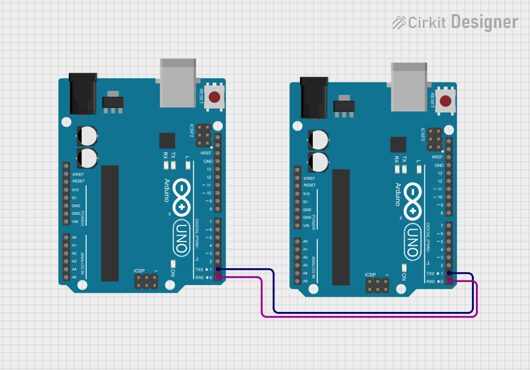
The circuit consists of two Arduino UNO microcontroller boards that are interconnected. The purpose of this configuration is not explicitly stated, but it can be inferred that the two boards are intended to communicate with each other via their serial ports. This is a common practice for sharing data or extending the number of available I/O pins by using multiple microcontrollers.
Component List
Arduino UNO
- Description: A microcontroller board based on the ATmega328P. It has 14 digital input/output pins, 6 analog inputs, a 16 MHz quartz crystal, a USB connection, a power jack, an ICSP header, and a reset button.
- Pins: UNUSED, IOREF, Reset, 3.3V, 5V, GND, Vin, A0, A1, A2, A3, A4, A5, SCL, SDA, AREF, D13, D12, D11, D10, D9, D8, D7, D6, D5, D4, D3, D2, D1, D0
Arduino UNO
- Description: Identical to the first Arduino UNO, used for extending capabilities or for separate tasks that require microcontroller processing.
- Pins: UNUSED, IOREF, Reset, 3.3V, 5V, GND, Vin, A0, A1, A2, A3, A4, A5, SCL, SDA, AREF, D13, D12, D11, D10, D9, D8, D7, D6, D5, D4, D3, D2, D1, D0
Wiring Details
Arduino UNO to Arduino UNO Connections
- D1: Serial TX (transmit) of the first Arduino UNO is connected to Serial TX of the second Arduino UNO.
- D0: Serial RX (receive) of the first Arduino UNO is connected to Serial RX of the second Arduino UNO.
Note: The above connections suggest a crossover serial connection, which is unusual. Typically, TX on one device should be connected to RX on the other device for serial communication. This might be an error in the wiring or a specific design choice for a particular reason.
Documented Code
Arduino UNO Code (First Microcontroller)
void setup() {
  // put your setup code here, to run once:

}

void loop() {
  // put your main code here, to run repeatedly:

}
Filename: sketch.ino
Arduino UNO Code (Second Microcontroller)
void setup() {
  // put your setup code here, to run once:

}

void loop() {
  // put your main code here, to run repeatedly:

}
Filename: sketch.ino
Note: Both microcontrollers have the same placeholder code, which does not perform any specific function. This code is likely a template and needs to be filled in with the actual logic that the microcontrollers are supposed to execute.
This documentation provides an overview of the circuit, including the components used, their wiring, and the code that runs on the microcontrollers. Further details may be required to fully understand the purpose and function of the circuit, which should be provided by the circuit designer.