
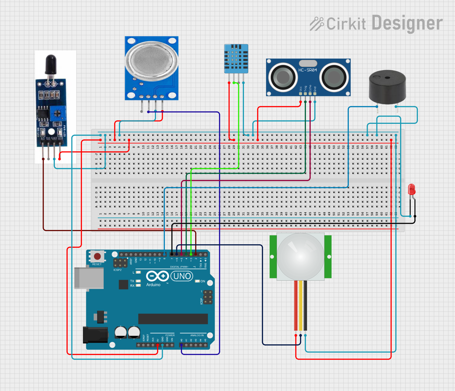
Circuit Documentation
Summary
The circuit in question is designed to interface with various sensors and output devices through an Arduino UNO microcontroller. The sensors include an HC-SR04 Ultrasonic Sensor, a PIR motion sensor, a DHT11 Humidity and Temperature Sensor, a Heat Flame Sensor, and an MQ135 air quality sensor. The output devices are a red LED and a buzzer. The circuit is powered by the 5V output from the Arduino UNO, and all components share a common ground with the microcontroller.
Component List
HC-SR04 Ultrasonic Sensor
- Pins: VCC, TRIG, ECHO, GND
- Description: This sensor measures distance by emitting ultrasonic waves and measuring the time taken for the echo to return.
PIR Sensor
- Pins: VDD, SIG, GND
- Description: A motion detection sensor that detects the presence of humans or animals by sensing changes in infrared levels.
LED: Two Pin (red)
- Pins: cathode, anode
- Description: A basic red LED used for indication purposes.
Buzzer
- Pins: PIN, GND
- Description: An audible alert device that emits a tone when powered.
Arduino UNO
- Pins: Various digital and analog I/O pins, power, and ground.
- Description: A microcontroller board based on the ATmega328P, used as the main controller for the circuit.
DHT11 Humidity and Temperature Sensor
- Pins: VDD, DATA, NULL, GND
- Description: A sensor that measures ambient temperature and humidity.
Heat Flame Sensor
- Pins: AO, DO, GND, VCC
- Description: A sensor that detects the presence of a flame or high temperatures.
MQ135 Air Quality Sensor
- Pins: VCC, GND, A0, D0
- Description: A sensor for detecting hazardous gases in the air.
Wiring Details
HC-SR04 Ultrasonic Sensor
- VCC: Connected to 5V on the Arduino UNO
- TRIG: Connected to Digital Pin D4 on the Arduino UNO
- ECHO: Connected to Digital Pin D5 on the Arduino UNO
- GND: Connected to GND on the Arduino UNO
PIR Sensor
- VDD: Connected to 5V on the Arduino UNO
- SIG: Connected to Digital Pin D6 on the Arduino UNO
- GND: Connected to GND on the Arduino UNO
LED: Two Pin (red)
- Cathode: Connected to GND on the Arduino UNO
- Anode: Connected to Digital Pin D7 on the Arduino UNO
Buzzer
- PIN: Connected to Digital Pin D8 on the Arduino UNO
- GND: Connected to GND on the Arduino UNO
DHT11 Humidity and Temperature Sensor
- VDD: Connected to 5V on the Arduino UNO
- DATA: Connected to Digital Pin D3 on the Arduino UNO
- GND: Connected to GND on the Arduino UNO
Heat Flame Sensor
- VCC: Connected to 5V on the Arduino UNO
- AO: Connected to Digital Pin D2 on the Arduino UNO
- GND: Connected to GND on the Arduino UNO
MQ135 Air Quality Sensor
- VCC: Connected to 5V on the Arduino UNO
- A0: Connected to Analog Pin A0 on the Arduino UNO
- GND: Connected to GND on the Arduino UNO
Documented Code
Arduino UNO Code (sketch.ino)
void setup() {
  // put your setup code here, to run once:

}

void loop() {
  // put your main code here, to run repeatedly:

}
Additional Notes (documentation.txt)
No additional code documentation was provided.