
ESP32-Controlled Smart Relay with Environmental Feedback and Alert System
View and Edit Project In Cirkit Designer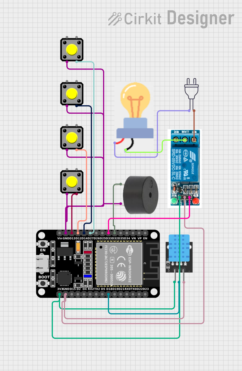
Circuit Documentation
Summary
The circuit in question appears to be a microcontroller-based system designed around the ESP32, a versatile and powerful microcontroller with Wi-Fi and Bluetooth capabilities. The circuit includes input devices (pushbuttons), output devices (buzzer, bulb), a sensor (DHT11 for temperature and humidity), and a relay module for controlling high-power devices. The ESP32's GPIO pins are used to interface with these components, allowing for various interactions such as sensing button presses, driving a buzzer, reading environmental data, and controlling a power bulb through a relay.
Component List
ESP32 (30 pin)
- Description: A microcontroller with Wi-Fi and Bluetooth capabilities.
- Pins: EN, VP, VN, D34, D35, D32, D33, D25, D26, D27, D14, D12, D13, GND, Vin, D23, D22, TX0, RX0, D21, D19, D18, D5, TX2, RX2, D4, D2, D15, 3V3.
Pushbutton
- Description: A simple switch mechanism for controlling a circuit.
- Pins: Pin 2, Pin 1, Pin 3, Pin 4.
Buzzer
- Description: An audio signaling device.
- Pins: PIN, GND.
DHT11
- Description: A sensor for measuring temperature and humidity.
- Pins: 5V, S, GND.
Bulb
- Description: An electric light with a wire filament heated until it glows.
- Pins: GND, power.
5v Relay
- Description: An electrically operated switch that allows you to turn on or off a circuit using a low-power signal.
- Pins: Normally Open, Common terminal, Normally Closed, In, GND, VCC.
Power 220v
- Description: A power supply module for high-voltage AC power.
- Pins: hot wire, neutral wire.
Wiring Details
ESP32 (30 pin)
- D32 connected to Buzzer PIN
- D33 connected to 5v Relay In
- D27 connected to Pushbutton Pin 3
- D14 connected to Pushbutton Pin 3
- D12 connected to Pushbutton Pin 3
- D13 connected to Pushbutton Pin 3
- GND connected to Pushbutton Pin 2, Buzzer GND, 5v Relay GND, DHT11 GND
- D18 connected to DHT11 S
- 3V3 connected to 5v Relay VCC, DHT11 5V
Pushbutton
- Pin 3 connected to ESP32 D27, D14, D12, D13
- Pin 2 connected to GND (shared with other pushbuttons, Buzzer, and 5v Relay)
Buzzer
- PIN connected to ESP32 D32
- GND connected to ESP32 GND
DHT11
- 5V connected to ESP32 3V3
- S connected to ESP32 D18
- GND connected to ESP32 GND
Bulb
- GND connected to 5v Relay Common terminal
- power connected to Power 220v hot wire
5v Relay
- In connected to ESP32 D33
- GND connected to ESP32 GND
- VCC connected to ESP32 3V3
- Common terminal connected to Bulb GND
- Normally Open connected to Power 220v neutral wire
Power 220v
- hot wire connected to Bulb power
- neutral wire connected to 5v Relay Normally Open
Documented Code
No code was provided for the microcontroller. The functionality of the circuit is dependent on the embedded code that would be running on the ESP32. The code would typically initialize the GPIO pins, set up the Wi-Fi or Bluetooth communication if needed, read inputs from the pushbuttons, control the buzzer and relay, and read data from the DHT11 sensor. Since no code is available, this section cannot be completed.