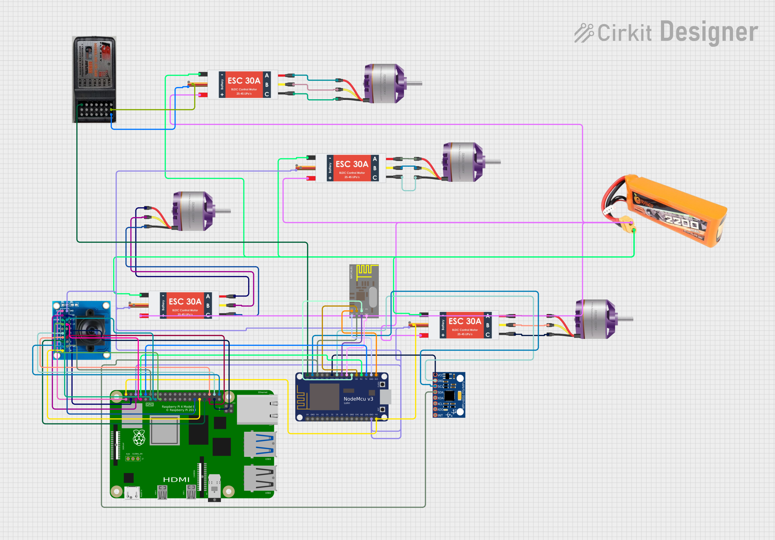
Wireless Multi-Motor Drone Control System with Video Streaming

Circuit Documentation
Summary
The circuit in question appears to be designed for a remote-controlled vehicle or drone, featuring brushless motors controlled by electronic speed controllers (ESCs), powered by a LiPo battery. It includes a microcontroller (NodeMCU V3 ESP8266) interfaced with an MPU-6050 sensor and an nRF24L01 wireless module for remote control capabilities. A Raspberry Pi 4B is used, possibly for higher-level control and processing, and an OV7725 camera module for vision capabilities. The RC receiver suggests the vehicle is controlled by a standard RC transmitter.
Component List
Brushless Motor
- Description: Motors that convert electrical energy into mechanical energy without brushes for commutation.
- Purpose: To provide propulsion for the vehicle.
Electronic Speed Controller (ESC)
- Description: Devices that regulate the speed and direction of the brushless motor.
- Purpose: To control the speed of the brushless motors based on input signals.
LiPo Battery 2200mAh 30C
- Description: A rechargeable battery with high energy density.
- Purpose: To provide power to the circuit.
RC Receiver 6 Channels
- Description: A receiver capable of receiving signals from an RC transmitter.
- Purpose: To receive control signals from the user's transmitter.
MPU-6050
- Description: A motion tracking device that contains a MEMS accelerometer and a MEMS gyro.
- Purpose: To provide motion sensing data such as acceleration and angular rate.
NodeMCU V3 ESP8266
- Description: A microcontroller board with Wi-Fi capabilities.
- Purpose: To process sensor data, control the ESCs, and communicate wirelessly.
nRF24L01
- Description: A wireless transceiver module that operates in the 2.4 GHz band.
- Purpose: To enable wireless communication for remote control.
Raspberry Pi 4B
- Description: A small single-board computer.
- Purpose: To perform higher-level processing and possibly control the camera module.
OV7725
- Description: A camera module capable of capturing images and video.
- Purpose: To provide vision capabilities for the vehicle.
Wiring Details
Brushless Motors
- Connected to their respective ESCs on pins L1, L2, L3.
Electronic Speed Controllers (ESCs)
- All ESCs are connected in parallel to the LiPo battery on pins Battery VCC and Battery GND.
- Each ESC's M1, M2, M3 pins are connected to a corresponding brushless motor.
- One ESC provides 5V output to the RC receiver.
- GND out pins of all ESCs are connected to the common ground net.
LiPo Battery 2200mAh 30C
- Provides power to the ESCs.
RC Receiver 6 Channels
- Powered by 5V and ground from one of the ESCs.
- CH1 is connected to the NodeMCU V3 ESP8266 for control signal input.
MPU-6050
- Powered by 3.3V from the NodeMCU V3 ESP8266.
- SCL and SDA are connected to the NodeMCU for I2C communication.
NodeMCU V3 ESP8266
- Receives power from one of the ESCs (Vin connected to 5V out).
- Interfaces with the MPU-6050, nRF24L01, and RC receiver for sensor data acquisition and wireless communication.
- Communicates with the Raspberry Pi 4B via serial connection (RX, TX).
nRF24L01
- Powered by 3.3V from the NodeMCU V3 ESP8266.
- CE, CSN, SCK, MOSI, MISO are connected to corresponding pins on the NodeMCU for SPI communication.
Raspberry Pi 4B
- Receives power from one of the ESCs (5V pin).
- Interfaced with the OV7725 camera module for vision processing.
- Communicates with the NodeMCU V3 ESP8266 via GPIO pins.
OV7725
- Powered by 3.3V from the Raspberry Pi 4B.
- Camera control and data pins are connected to corresponding GPIO pins on the Raspberry Pi 4B.
Documented Code
NodeMCU V3 ESP8266 Code (sketch.ino)
#include <SPI.h>
#include <nRF24L01.h>
#include <RF24.h>

RF24 radio(D2, D8); // CE, CSN
const byte address[5] = "00001";

struct Data_Package {
  int throttle;
  int yaw;
  int pitch;
  int roll;
};

Data_Package data;

void setup() {
  Serial.begin(9600);
  radio.begin();
  radio.openWritingPipe(address);
  radio.setPALevel(RF24_PA_MIN);
  radio.stopListening();
}

void loop() {
  // Read joystick values
  data.throttle = analogRead(A0); // X-axis
  data.yaw = analogRead(D1); // Y-axis
  data.pitch = 0; // Placeholder for pitch control
  data.roll = 0; // Placeholder for roll control

  // Print joystick values for debugging
  Serial.print("Throttle: ");
  Serial.print(data.throttle);
  Serial.print(" Yaw: ");
  Serial.print(data.yaw);
  Serial.print(" Pitch: ");
  Serial.print(data.pitch);
  Serial.print(" Roll: ");
  Serial.println(data.roll);

  // Send data package
  radio.write(&data, sizeof(Data_Package));
  delay(50); // Adjust delay as needed
}
This code is responsible for reading control inputs from an analog joystick connected to the NodeMCU, packaging the data into a structure, and transmitting it wirelessly via the nRF24L01 module. The Data_Package structure holds the throttle and yaw values, with placeholders for pitch and roll. The values are printed to the serial monitor for debugging purposes and sent out at a regular interval (50 ms).