
IR Sensor and Relay-Controlled Motor and Water Pump System with Battery Power
View and Edit Project In Cirkit Designer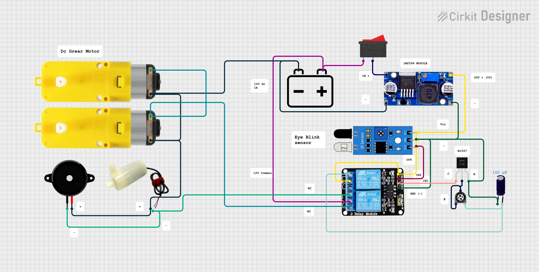
Circuit Documentation
Summary
This circuit involves various components including a trimmer potentiometer, relay module, IR sensor, rocker switch, battery, voltage regulator, transistor, capacitor, piezo speaker, motor with reducer, and a water pump. The circuit is designed to control the operation of motors and a water pump based on the input from an IR sensor, with the relay module acting as a switch.
Component List
Trimmer Potentiometer
- Description: Adjustable resistor used to vary resistance in the circuit.
- Pins: leg1, wiper, leg2
- Properties: Resistance: 100k Ohms
5V 2-Relay JD-VCC
- Description: Relay module used to control high voltage devices.
- Pins: JD-VCC, VCC, GND, IN1, IN2, NO, COM, NC
IR Sensor
- Description: Sensor used to detect infrared light.
- Pins: out, gnd, vcc
Rocker Switch
- Description: Switch used to control the flow of current.
- Pins: 1, 2
12V Battery
- Description: Power source for the circuit.
- Pins: -, +
LM2596
- Description: Voltage regulator used to step down voltage.
- Pins: IN, OUT
BC547
- Description: NPN transistor used for switching and amplification.
- Pins: collector, base, emitter
Electrolytic Capacitor
- Description: Capacitor used to store electrical energy.
- Pins: -, +
- Properties: Capacitance: 100µF
Piezo Speaker
- Description: Speaker used to produce sound.
- Pins: pin1, pin2
Motor with Reducer
- Description: Motor with a gear reducer.
- Pins: 3 - 6 VCC, GND
5V Mini Water Pump
- Description: Water pump used to move water.
- Pins: positive pin, negative pin
Wiring Details
Trimmer Potentiometer
- leg1 is connected to wiper and base of BC547.
- leg2 is connected to NO of 5V 2-Relay JD-VCC and + of Electrolytic Capacitor.
5V 2-Relay JD-VCC
- NO is connected to leg2 of Trimmer Potentiometer and + of Electrolytic Capacitor.
- GND is connected to gnd of IR Sensor, - of Electrolytic Capacitor, Emitter of BC547, and OUT of LM2596.
- IN1 is connected to collector of BC547.
- IN2 is connected to out of IR Sensor.
- VCC is connected to COM of 5V 2-Relay JD-VCC, vcc of IR Sensor, and OUT of LM2596.
- COM is connected to 1 of Rocker Switch and + of 12V Battery.
- NC is connected to 3 - 6 VCC of both Motors with Reducer.
IR Sensor
- gnd is connected to GND of 5V 2-Relay JD-VCC.
- out is connected to IN2 of 5V 2-Relay JD-VCC.
- vcc is connected to VCC of 5V 2-Relay JD-VCC.
Rocker Switch
- 1 is connected to COM of 5V 2-Relay JD-VCC.
- 2 is connected to IN of LM2596.
12V Battery
- + is connected to COM of 5V 2-Relay JD-VCC.
- - is connected to GND of Motor with Reducer, pin2 of Piezo Speaker, positive pin of 5V Mini Water Pump, GND of Motor with Reducer, and IN of LM2596.
LM2596
- IN is connected to 2 of Rocker Switch and - of 12V Battery.
- OUT is connected to GND of 5V 2-Relay JD-VCC and VCC of 5V 2-Relay JD-VCC.
BC547
- collector is connected to IN1 of 5V 2-Relay JD-VCC.
- base is connected to leg1 and wiper of Trimmer Potentiometer.
- Emitter is connected to GND of 5V 2-Relay JD-VCC.
Electrolytic Capacitor
- + is connected to leg2 of Trimmer Potentiometer and NO of 5V 2-Relay JD-VCC.
- - is connected to GND of 5V 2-Relay JD-VCC.
Piezo Speaker
- pin1 is connected to NO of 5V 2-Relay JD-VCC.
- pin2 is connected to - of 12V Battery.
Motor with Reducer
- 3 - 6 VCC is connected to NC of 5V 2-Relay JD-VCC.
- GND is connected to - of 12V Battery.
5V Mini Water Pump
- positive pin is connected to - of 12V Battery.
- negative pin is connected to NO of 5V 2-Relay JD-VCC.
Documented Code
sketch.ino
void setup() {
  // put your setup code here, to run once:

}

void loop() {
  // put your main code here, to run repeatedly:

}
documentation.txt