
Arduino Pro Mini Based GPS and Temperature Tracking System with Wireless Communication
View and Edit Project In Cirkit Designer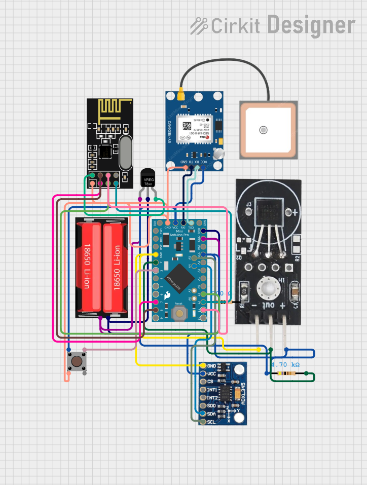
Circuit Documentation
Summary
This circuit integrates a variety of components to perform multiple functions, including temperature sensing, acceleration measurement, wireless communication, and GPS location tracking. The core of the circuit is an Arduino Pro Mini, which controls the sensors and communication modules. A DS18B20 temperature sensor provides temperature readings, while an ADXL345 accelerometer measures acceleration forces. The GPS NEO 6M module allows for location tracking. Wireless communication is facilitated by the NRF24L01 module. Power management is handled by a voltage regulator, which steps down the voltage from an 18650 Li-Ion battery to the required levels for the circuit. A pushbutton is included for user input, and resistors are used for pull-ups and voltage division as needed.
Component List
Arduino Pro Mini
A compact microcontroller board based on the ATmega328, which is used as the main controller for the circuit.
DS18B20 Temperature Sensor
A digital temperature sensor that provides temperature readings over a one-wire interface.
GPS NEO 6M
A GPS module that provides location data.
ADXL345
A digital accelerometer that measures acceleration forces.
NRF24L01
A wireless communication module that operates in the 2.4 GHz band.
Voltage Regulator
A component that steps down the input voltage to a stable output voltage.
Pushbutton
A simple switch that allows for user input.
Resistor (200 Ohms)
A resistor with a resistance of 200 Ohms, possibly used for current limiting or pull-up/down configurations.
Resistor (4700 Ohms)
A resistor with a resistance of 4700 Ohms, possibly used for current limiting or pull-up/down configurations.
18650 Li-Ion Battery
A rechargeable battery that provides power to the circuit.
Wiring Details
Arduino Pro Mini
TXOconnected to GPS NEO 6MRXRXIconnected to GPS NEO 6MTXVCCconnected to common VCC net (with other components)GNDconnected to common GND net (with other components)A4connected to ADXL345SDAA5connected to ADXL345SCLRAWconnected to Voltage RegulatorOUTD2connected to DS18B20 Temperature SensorOUT(via 4700 Ohms resistor)D3connected to PushbuttonPin 3 (out)D7connected to NRF24L01CED8connected to NRF24L01CSNMISOconnected to NRF24L01MISOMOSIconnected to NRF24L01MOSISCKconnected to NRF24L01SCK
DS18B20 Temperature Sensor
VCCconnected to common VCC net (via 4700 Ohms resistor)OUTconnected to Arduino Pro MiniD2(via 4700 Ohms resistor)GNDconnected to common GND net
GPS NEO 6M
VCCconnected to common VCC netRXconnected to Arduino Pro MiniTXOTXconnected to Arduino Pro MiniRXIGNDconnected to common GND net
ADXL345
VCCconnected to common VCC netGNDconnected to common GND netSDAconnected to Arduino Pro MiniA4SCLconnected to Arduino Pro MiniA5
NRF24L01
VCC (3V)connected to Voltage RegulatorOUTGNDconnected to common GND netCEconnected to Arduino Pro MiniD7CSNconnected to Arduino Pro MiniD8SCKconnected to Arduino Pro MiniSCKMISOconnected to Arduino Pro MiniMISOMOSIconnected to Arduino Pro MiniMOSI
Voltage Regulator
INconnected to 18650 Li-Ion BatteryPositiveGNDconnected to 18650 Li-Ion BatteryNegativeOUTconnected to Arduino Pro MiniRAWand NRF24L01VCC (3V)
Pushbutton
Pin 1 (in)connected to common VCC netPin 2 (in)connected to common GND netPin 3 (out)connected to Arduino Pro MiniD3
Resistor (200 Ohms)
pin1andpin2not detailed in the net list.
Resistor (4700 Ohms)
pin1connected to common VCC netpin2connected to DS18B20 Temperature SensorOUTand Arduino Pro MiniD2
18650 Li-Ion Battery
Positiveconnected to Voltage RegulatorINNegativeconnected to Voltage RegulatorGND
Documented Code
Arduino Pro Mini (sketch.ino)
void setup() {
  // put your setup code here, to run once:

}

void loop() {
  // put your main code here, to run repeatedly:

}
Arduino Pro Mini (documentation.txt)
No additional documentation provided for the code.