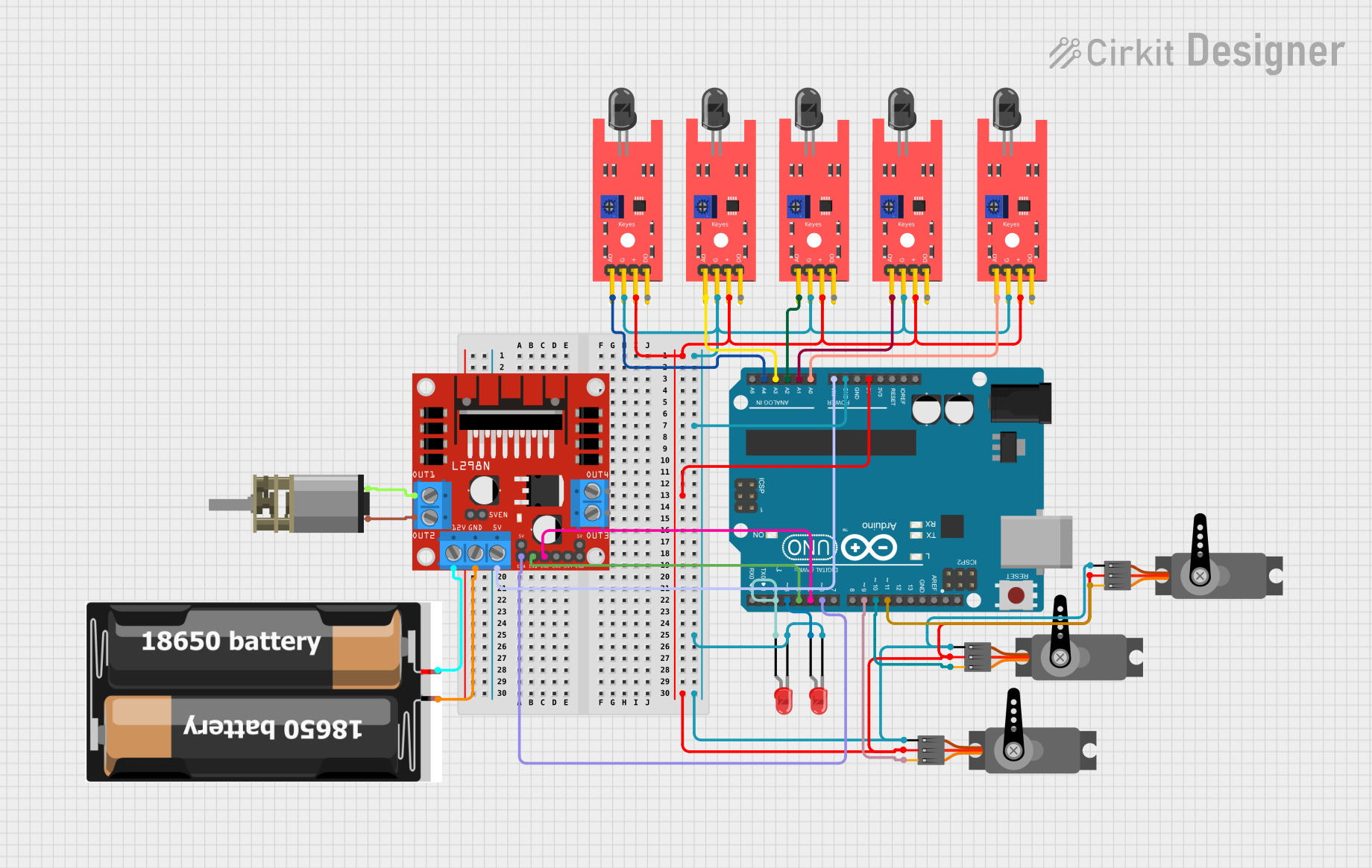
Arduino UNO Based Flame Detection and Motor Control System

Circuit Documentation
Summary
This circuit is designed to interface multiple sensors and actuators with an Arduino UNO microcontroller. It includes flame sensors for detecting fire or flames, LEDs for indication, servos for actuation, and a DC motor with a driver for motion control. The power supply is provided by a 2x 18650 battery pack, and the motor driver is capable of handling the motor's power requirements. The circuit is likely intended for a fire detection and response application, where the flame sensors detect the presence of fire, the LEDs provide visual status, and the servos and motor perform some form of physical response.
Component List
- KY-026 Flame Sensor: A sensor capable of detecting fire or flames, typically used in fire alarm systems.
- Arduino UNO: A microcontroller board based on the ATmega328P, widely used for building digital devices and interactive objects.
- LED (Red): A two-pin light-emitting diode that emits red light, commonly used as an indicator.
- Servo: An actuator that can be precisely controlled for angular or linear position, speed, and acceleration.
- DC Mini Metal Gear Motor: A small-sized, geared DC motor used for applications requiring low speed and high torque.
- L298N DC Motor Driver: A motor driver module capable of driving two DC motors or one stepper motor.
- 2x 18650 Battery Pack: A power source consisting of two 18650 lithium-ion rechargeable batteries.
Wiring Details
KY-026 Flame Sensor
- VCC: Connected to the 5V output from the Arduino UNO.
- GND: Connected to the ground (GND) on the Arduino UNO.
- A0: Analog output connected to an analog input on the Arduino UNO (varies per sensor instance).
- D0: Digital output (not used in this circuit).
Arduino UNO
- 5V: Provides power to the flame sensors and servos.
- GND: Common ground for the entire circuit.
- A0 - A5: Analog inputs connected to the A0 pins of the flame sensors.
- D2, D3: Digital outputs connected to the anodes of the red LEDs.
- D4, D5, D6, D9, D10, D11: Digital outputs connected to the motor driver and servos.
- Vin: Connected to the 5V input on the L298N motor driver.
LED (Red)
- Anode: Connected to a digital output on the Arduino UNO (D2 or D3).
- Cathode: Connected to the ground (GND) on the Arduino UNO.
Servo
- VCC: Connected to the 5V output from the Arduino UNO.
- GND: Connected to the ground (GND) on the Arduino UNO.
- PWM: Pulse Width Modulation input connected to a digital output on the Arduino UNO (D9, D10, or D11).
DC Mini Metal Gear Motor
- IN1, IN2: Inputs from the L298N motor driver (OUT1, OUT2).
L298N DC Motor Driver
- OUT1, OUT2: Outputs connected to the DC Mini Metal Gear Motor.
- 12V: Power input connected to the 2x 18650 battery pack.
- GND: Ground connected to the 2x 18650 battery pack.
- 5V: Logic power input connected to the Vin on the Arduino UNO.
- ENA, IN1, IN2: Control inputs connected to digital outputs on the Arduino UNO (D4, D5, D6).
2x 18650 Battery Pack
- VCC: Connected to the 12V input on the L298N motor driver.
- GND: Connected to the ground (GND) on the L298N motor driver.
Documented Code
void setup() {
  // put your setup code here, to run once:

}

void loop() {
  // put your main code here, to run repeatedly:

}
The provided code is a template with empty setup() and loop() functions, which are the entry points for Arduino sketches. The setup() function is intended for initialization code that runs once, while the loop() function contains code that runs repeatedly, forming the main logic of the program. Actual implementation details need to be filled in based on the specific requirements of the circuit's application.