Arduino UNO Based Water Flow Monitoring System with OLED Display and Rotary Encoder
Circuit Documentation
Summary
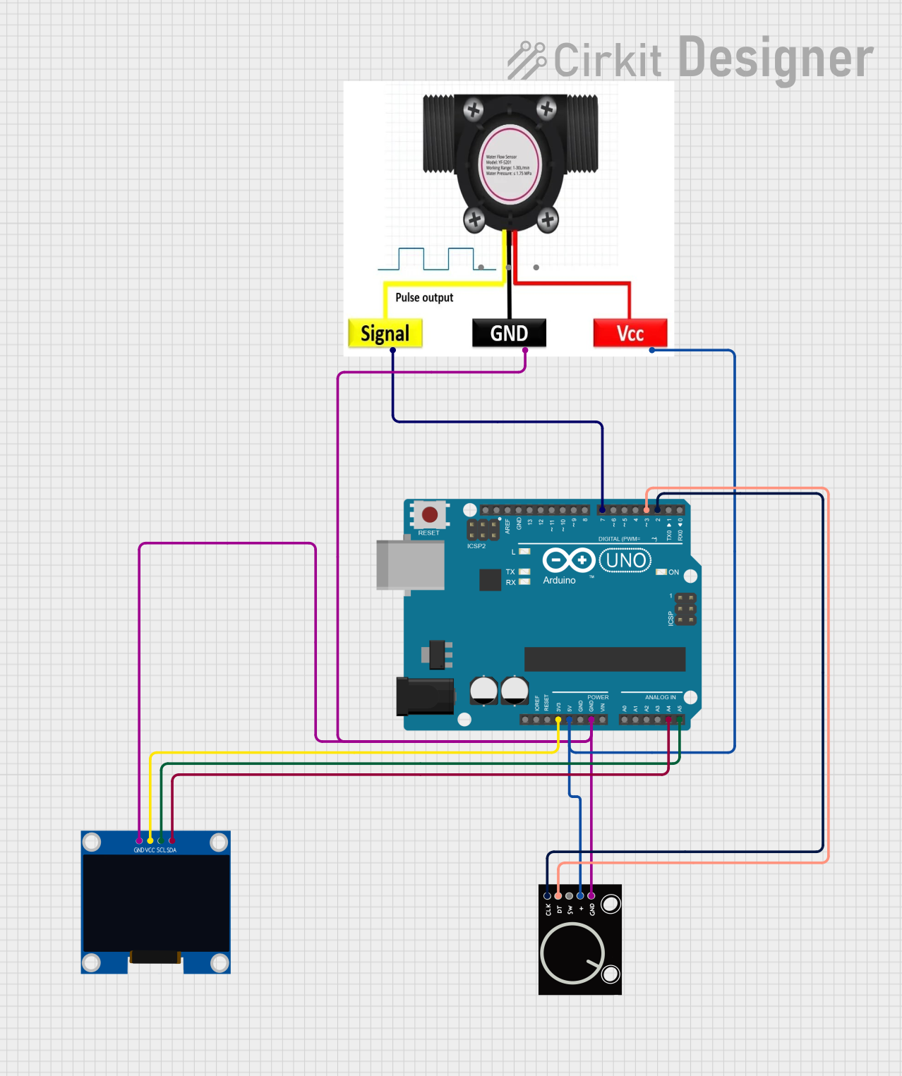
The circuit in question is designed to measure water flow using a water flow meter and display the data on an OLED display. It also includes a rotary encoder to allow user interaction. The Arduino UNO serves as the central microcontroller unit to process the sensor data, manage the display, and read the rotary encoder inputs.
Component List
Arduino UNO
- Description: A microcontroller board based on the ATmega328P.
- Purpose: Acts as the central processing unit for the circuit, reading sensor data, controlling the OLED display, and interfacing with the rotary encoder.
Rotary Encoder
- Description: An input device that provides rotational position feedback.
- Purpose: Allows the user to input data or navigate through the system's interface.
128x64 OLED Display (I2C IIC SPI Serial)
- Description: A small display that uses organic light-emitting diodes.
- Purpose: Displays information such as water flow rate and total volume.
WATER FLOW METER
- Description: A sensor that measures the flow rate of water.
- Purpose: Provides real-time data on the volume of water passing through it.
Wiring Details
Arduino UNO
- 3.3V connected to OLED Display VCC
- 5V connected to Rotary Encoder "+" and WATER FLOW METER VCC
- GND connected to Rotary Encoder GND, WATER FLOW METER GND, and OLED Display GND
- A4 (SDA) connected to OLED Display SDA
- A5 (SCL) connected to OLED Display SCL
- D7 connected to WATER FLOW METER SIG
- D3 connected to Rotary Encoder DT
- D2 connected to Rotary Encoder CLK
Rotary Encoder
- GND connected to Arduino UNO GND
- + connected to Arduino UNO 5V
- SW (Switch) not connected
- DT connected to Arduino UNO D3
- CLK connected to Arduino UNO D2
128x64 OLED Display (I2C IIC SPI Serial)
- GND connected to Arduino UNO GND
- SDA connected to Arduino UNO A4 (SDA)
- SCL connected to Arduino UNO A5 (SCL)
- VCC connected to Arduino UNO 3.3V
WATER FLOW METER
- SIG connected to Arduino UNO D7
- GND connected to Arduino UNO GND
- VCC connected to Arduino UNO 5V
Documented Code
The code for the Arduino UNO microcontroller is written in C++ and is designed to be compiled and uploaded using the Arduino IDE. The code is responsible for initializing the components, reading sensor data from the water flow meter, processing the rotary encoder input, and updating the OLED display with the relevant information.
// Include necessary libraries
#include <Arduino.h>
#include <U8g2lib.h>
#include <PinChangeInterrupt.h>
#include <NewEncoder.h>

// Define pins and variables
byte sensorPin = 7;
byte sensorInterrupt = digitalPinToPCINT(sensorPin);
float calibrationFactor = 4.5;
volatile byte pulseCount;
float flowRate;
unsigned int flowMilliLitres;
unsigned long totalMilliLitres;
unsigned long oldTime;

// Function to count pulses from the water flow sensor
void pulseCounter() {
  pulseCount++;
}

// Setup function for the gas flow sensor
void gasFlowSetup() {
  Serial.begin(9600);
  pinMode(sensorPin, INPUT);
  digitalWrite(sensorPin, HIGH);
  pulseCount = 0;
  flowRate = 0.0;
  flowMilliLitres = 0;
  totalMilliLitres = 0;
  oldTime = 0;
  attachPCINT(sensorInterrupt, pulseCounter, FALLING);
}

// Function to read the gas flow rate
void readGasFlow() {
  if ((millis() - oldTime) > 1000) {
    detachPCINT(sensorInterrupt);
    flowRate = ((1000.0 / (millis() - oldTime)) * pulseCount) / calibrationFactor;
    oldTime = millis();
    flowMilliLitres = (flowRate / 60) * 1000;
    totalMilliLitres += flowMilliLitres;
    Serial.print("Flow rate: ");
    Serial.print(int(flowRate));
    Serial.print("L/min");
    Serial.print("\t");
    Serial.print("Output Liquid Quantity: ");
    Serial.print(totalMilliLitres);
    Serial.println("mL");
    Serial.print("\t");
    Serial.print(totalMilliLitres / 1000);
    Serial.print("L");
    pulseCount = 0;
    attachPCINT(sensorInterrupt, pulseCounter, FALLING);
  }
}

// Additional code for the rotary encoder and OLED display is omitted for brevity
// ...

// Arduino setup function
void setup() {
  switchSetup();
  displaySetup();
  gasFlowSetup();
}

// Arduino main loop function
void loop() {
  u8g2.firstPage();
  do {
    readIntakeSwitch();
    readGasFlow();
    draw();
  } while (u8g2.nextPage());
}
The code above includes the setup and main loop functions, as well as the necessary interrupt service routines to handle the water flow meter's pulse output. It also initializes the OLED display and processes the rotary encoder input. The full code would include additional functions and logic to handle the display and encoder, which are not shown here for brevity.