ESP32-Based Multi-Functional IoT Device with GSM and Camera Modules
Circuit Documentation
Summary
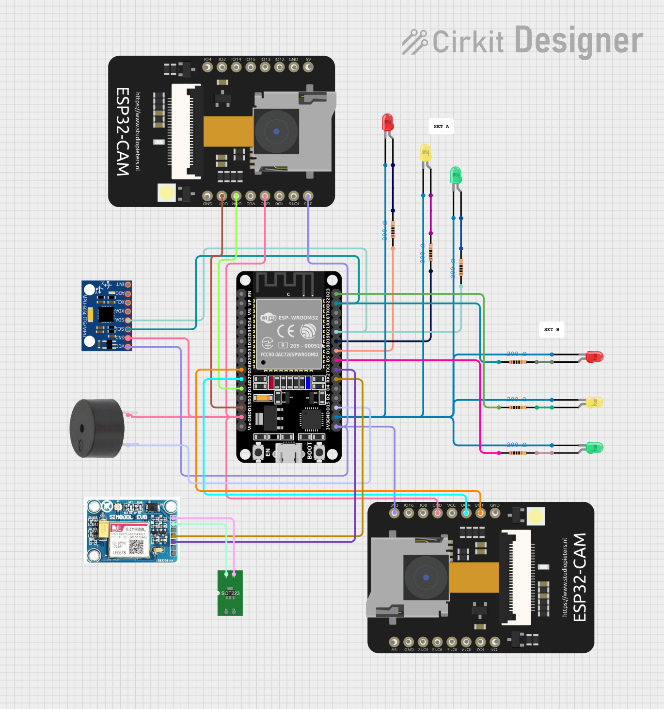
The circuit in question appears to be a microcontroller-based system utilizing an ESP32 (30 pin) as the central processing unit. The circuit includes a variety of peripherals such as LEDs of different colors (red, green, yellow), resistors, an MPU-6050 sensor, two ESP32 CAM modules, a buzzer, a SIM 800L V2.0 GSM module, and a voltage regulator LM1117. The ESP32 microcontroller interfaces with these components through various GPIO pins, and the circuit is designed to perform multiple functions, possibly including motion detection, wireless communication, and visual indication through LEDs.
Component List
Resistors
- Resistor (200 Ohms): Used for current limiting and voltage division in the circuit.
LEDs
- LED: Two Pin (red)
- LED: Two Pin (green)
- LED: Two Pin (yellow): These LEDs are used as visual indicators and are connected with resistors to limit the current through them.
Microcontrollers
- ESP32 (30 pin): The main microcontroller that controls the circuit.
- ESP32 CAM: A camera module with Wi-Fi capabilities, used for capturing images and possibly for video streaming.
Sensors and Modules
- MPU-6050: A motion tracking device that contains a 3-axis gyroscope and a 3-axis accelerometer.
- SIM 800L V2.0 GSM: A GSM module for cellular communication.
- Voltage Regulator LM1117: Used to regulate the voltage supplied to the SIM 800L GSM module.
Other
- Buzzer: An audible signaling device.
Wiring Details
Resistors
- Resistor (200 Ohms)
- One end connected to an ESP32 GPIO pin.
- The other end connected to the anode of an LED.
LEDs
- LED: Two Pin (red/green/yellow)
- Anode connected to a resistor.
- Cathode connected to the ESP32 GND pin.
ESP32 (30 pin)
- GPIO pins connected to resistors and LEDs.
- GND pin connected to the cathodes of all LEDs, the GND pins of the MPU-6050, ESP32 CAM, buzzer, and SIM 800L GSM module.
- 3V3 pin connected to the 3.3V pins of the ESP32 CAM and MPU-6050.
- TX2/RX2 pins connected to the SIM 800L GSM module for serial communication.
- D15 pin connected to the buzzer.
ESP32 CAM
- GPIO1 / TX and GPIO3 / RX connected to the ESP32 for serial communication.
- GND pin connected to the ESP32 GND pin.
- 3.3V pin connected to the ESP32 3V3 pin.
MPU-6050
- SDA and SCL connected to the ESP32 for I2C communication.
- VCC connected to the ESP32 3V3 pin.
- GND connected to the ESP32 GND pin.
SIM 800L V2.0 GSM
- SIM.RXD and SIM_TXD connected to the ESP32 TX2 and RX2 pins for serial communication.
- 5V/4V connected to the IN pin of the voltage regulator LM1117.
- GND connected to the OUT pin of the voltage regulator LM1117.
Voltage Regulator LM1117
- IN pin connected to the 5V/4V pin of the SIM 800L GSM module.
- OUT pin connected to the GND pin of the SIM 800L GSM module.
Buzzer
- PIN connected to an ESP32 GPIO pin.
- GND connected to the ESP32 GND pin.
Documented Code
No code was provided for the microcontrollers in the circuit. Therefore, this section is left blank until the relevant code is supplied. The code would typically include initialization and configuration of the microcontroller's peripherals, the main control loop, and functions for handling communication with the modules and sensors, as well as driving the LEDs and buzzer based on the logic defined in the application.