
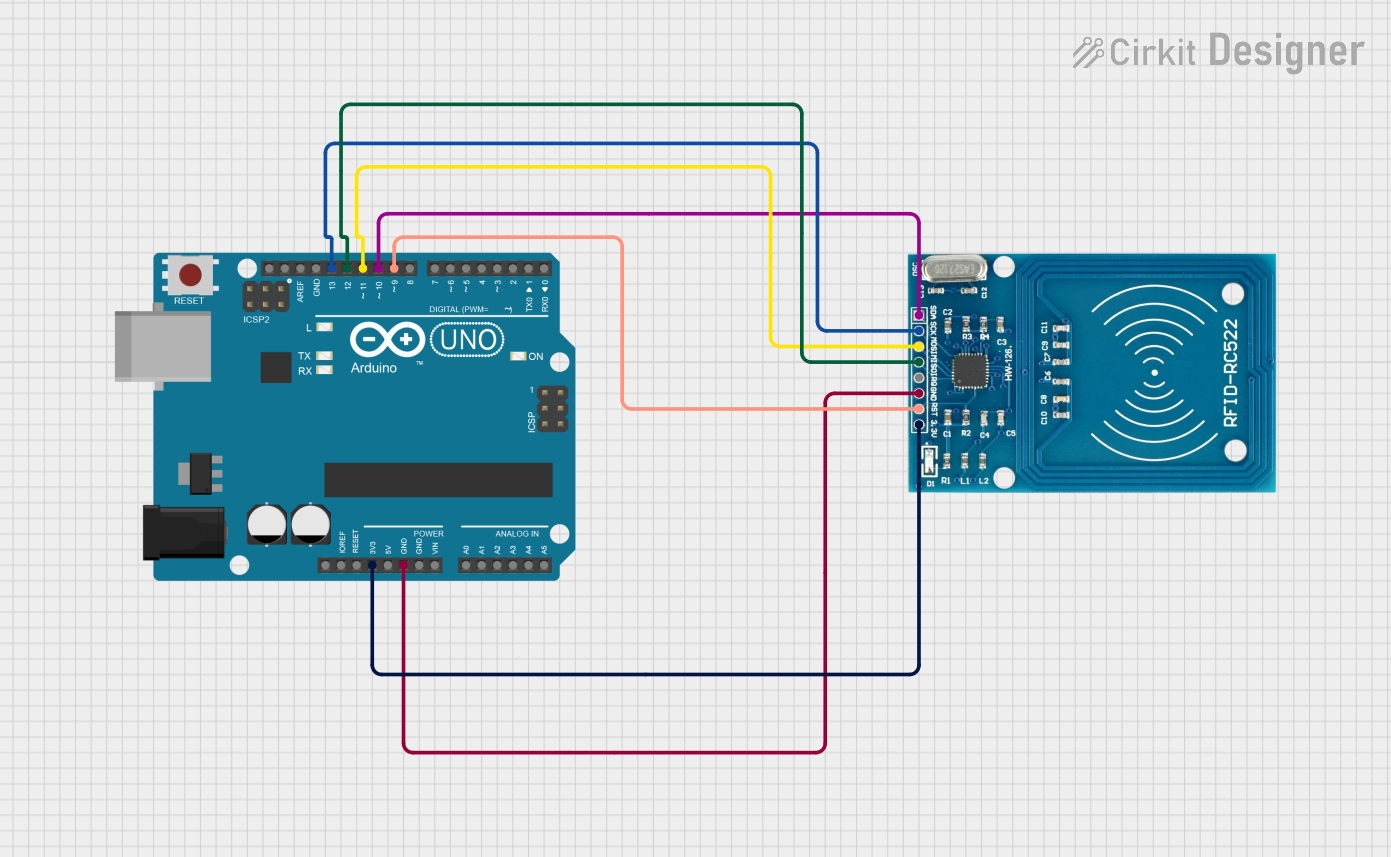
Circuit Documentation
Summary
This document provides a detailed overview of a circuit that integrates an RFID-RC522 module with an Arduino UNO microcontroller. The purpose of the circuit is to read data from RFID tags or cards using the RFID-RC522 module and communicate the information to a connected computer via the Arduino UNO. The Arduino UNO is programmed to initialize the RFID reader, handle the detection of new RFID cards, and output the card information to the serial monitor.
Component List
RFID-RC522
- Description: An RFID reader/writer module for contactless communication at 13.56MHz.
- Pins: VCC (3.3V), RST, GND, IRQ, MISO, MOSI, SCK, SDA
Arduino UNO
- Description: A microcontroller board based on the ATmega328P, commonly used for building digital devices and interactive objects that can sense and control objects in the physical world.
- Pins: UNUSED, IOREF, Reset, 3.3V, 5V, GND, Vin, A0-A5, SCL, SDA, AREF, D0-D13
Wiring Details
RFID-RC522
- VCC (3.3V): Connected to the 3.3V pin on the Arduino UNO.
- RST: Connected to digital pin D9 on the Arduino UNO.
- GND: Connected to one of the GND pins on the Arduino UNO.
- MISO: Connected to digital pin D12 on the Arduino UNO.
- MOSI: Connected to digital pin D11 on the Arduino UNO.
- SCK: Connected to digital pin D13 on the Arduino UNO.
- SDA: Connected to digital pin D10 on the Arduino UNO.
Arduino UNO
- 3.3V: Provides power to the RFID-RC522 module.
- D9: Acts as the reset pin for the RFID-RC522 module.
- GND: Common ground for the circuit.
- D12 (MISO): Receives data from the RFID-RC522 module's MISO pin.
- D11 (MOSI): Sends data to the RFID-RC522 module's MOSI pin.
- D13 (SCK): Provides the clock signal to the RFID-RC522 module's SCK pin.
- D10 (SDA): Acts as the Slave Select (SS) for the RFID-RC522 module.
Documented Code
The following code is written for the Arduino UNO to interface with the RFID-RC522 module. It initializes the RFID reader and continuously checks for new RFID cards to read their UID and other data.
#include <SPI.h>
#include <MFRC522.h>

#define RST_PIN         9          // Configurable, see typical pin layout above
#define SS_PIN          10         // Configurable, see typical pin layout above

MFRC522 mfrc522(SS_PIN, RST_PIN);  // Create MFRC522 instance

void setup() {
    Serial.begin(9600);        // Initialize serial communications with the PC
    while (!Serial);           // Do nothing if no serial port is opened (added for Arduinos based on ATMEGA32U4)
    SPI.begin();               // Init SPI bus
    mfrc522.PCD_Init();        // Init MFRC522
    delay(4);                  // Optional delay. Some board do need more time after init to be ready, see Readme
    mfrc522.PCD_DumpVersionToSerial();    // Show details of PCD - MFRC522 Card Reader details
    Serial.println(F("Scan PICC to see UID, SAK, type, and data blocks..."));
}

void loop() {
    // Reset the loop if no new card present on the sensor/reader. This saves the entire process when idle.
    if ( ! mfrc522.PICC_IsNewCardPresent()) {
        return;
    }

    // Select one of the cards
    if ( ! mfrc522.PICC_ReadCardSerial()) {
        return;
    }

    // Dump debug info about the card; PICC_HaltA() is automatically called
    mfrc522.PICC_DumpToSerial(&(mfrc522.uid));
}
This code is designed to be uploaded to the Arduino UNO using the Arduino IDE. Once uploaded, the Arduino will communicate with the RFID-RC522 module to read RFID cards and output the information to the serial monitor.