9V Battery-Powered Blue LED Array with ELE Generator
Circuit Documentation
Summary of the Circuit
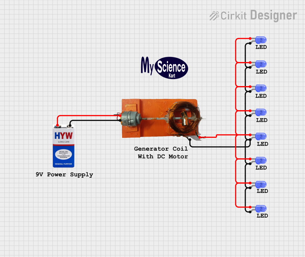
The circuit described by the provided inputs consists of an electrical power source, an electrical generator, and multiple LEDs. The power source is a 9V battery, which is connected to an electrical generator. The generator is then connected to a series of blue two-pin LEDs. The LEDs are arranged such that their anodes are all connected to one terminal of the generator, and their cathodes are connected to the other terminal. This configuration suggests that the LEDs are intended to be powered by the generator, which in turn is connected to the battery. There is no microcontroller or embedded code involved in this circuit.
Component List
ELE Generator
- Description: An electrical generator component that likely converts mechanical energy into electrical energy.
- Purpose: To provide electrical power to the LEDs in the circuit.
9V Battery
- Description: A standard 9V battery used as the power source.
- Purpose: To supply electrical power to the generator, which in turn powers the LEDs.
LEDs: Two Pin (blue)
- Description: Light Emitting Diodes (LEDs) that emit blue light.
- Purpose: To emit light when powered by the generator.
Logo
- Description: A graphical representation or branding element with no electrical function.
- Purpose: Likely used for aesthetic or branding purposes within the circuit design.
Comments
- Description: Textual annotations that provide additional information or instructions.
- Purpose: To convey messages or notes to the circuit designer or user.
Wiring Details
ELE Generator
- Connected to the positive terminal of the 9V battery.
- Connected to the anodes of all the blue LEDs.
- Connected to the cathodes of all the blue LEDs.
9V Battery
- Positive terminal connected to the ELE Generator.
- Negative terminal connected to the ELE Generator.
LEDs: Two Pin (blue)
- Anodes of all LEDs connected to one terminal of the ELE Generator.
- Cathodes of all LEDs connected to the other terminal of the ELE Generator.
Documented Code
There is no embedded code provided for this circuit as there are no microcontroller components included in the design. Therefore, no code documentation is necessary for this circuit.
This documentation provides an overview of the circuit's components and their interconnections. It should be noted that the actual functionality of the ELE Generator is not specified, and the circuit does not include any current-limiting resistors for the LEDs, which are typically necessary to prevent damage to the LEDs. If this is an oversight, it is recommended to include current-limiting resistors in series with each LED to ensure safe operation.