Cirkit Designer
Your all-in-one circuit design IDE
Home /
Project Documentation
Arduino UNO-Based Alcohol Detection and GPS Tracking System with SMS Alerts
Circuit Documentation
Summary
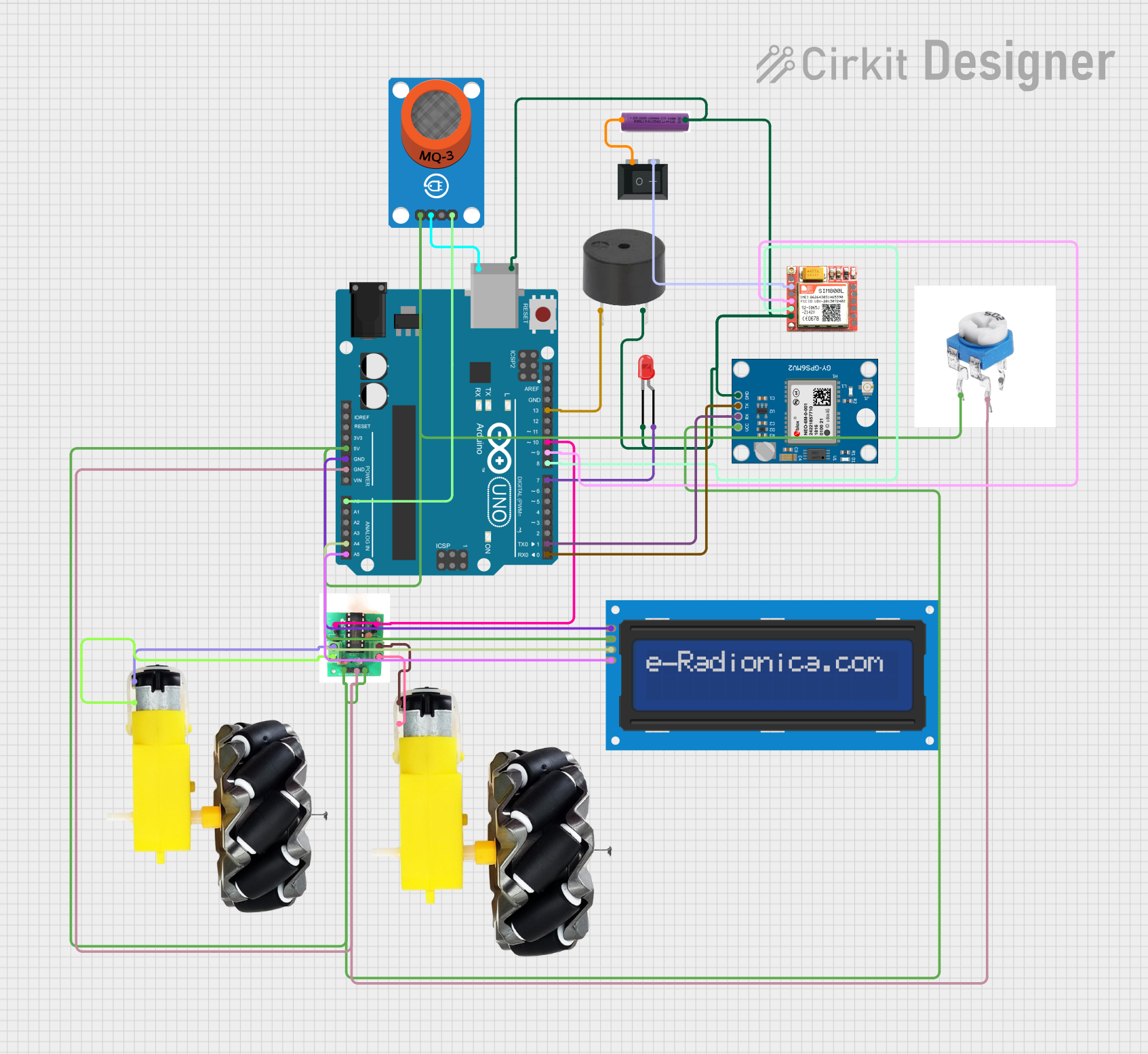
This circuit is designed to monitor alcohol levels using an MQ-3 sensor and take appropriate actions based on the readings. It includes a GPS module for location tracking, a GSM module for sending SMS alerts, and a motor control system. The circuit also features an LCD display for real-time data visualization and a buzzer for audible alerts.
Component List
Buzzer
- Pins: PIN, GND
- Description: Emits an audible sound when activated.
- Purpose: Alerts the user when the alcohol level exceeds a predefined threshold.
LED: Two Pin (red)
- Pins: Cathode, Anode
- Description: A red LED.
- Purpose: Indicates the status of the system.
MQ-3 Breakout
- Pins: VCC, GND, DO, AO
- Description: Alcohol sensor.
- Purpose: Detects alcohol levels in the environment.
3.7v Battery
- Pins: +, -
- Description: Power source.
- Purpose: Supplies power to the circuit.
Rocker Switch (SPST)
- Pins: 1, 2
- Description: Single Pole Single Throw switch.
- Purpose: Turns the circuit on and off.
SIM 800L
- Pins: NFT, RING, VCC, DTR, RST, MIC +, RXD, MIC-, TXD, SPK+, GND, SPK-
- Description: GSM module.
- Purpose: Sends SMS alerts.
Neo 6M GPS Module
- Pins: GND, TX, RX, VCC
- Description: GPS module.
- Purpose: Provides location data.
Motor and Wheels
- Pins: VCC, GND
- Description: Motor with wheels.
- Purpose: Controls the movement of the system.
5k Preset
- Pins: Fixed end 1, Fixed end 2, Variable end
- Description: Adjustable resistor.
- Purpose: Adjusts the sensitivity of the MQ-3 sensor.
L293D Motor Driver
- Pins: GND, 9/12 volts, 5 volts, Motor input 1, Motor input 2, +v1, -v1, +v2, -v2
- Description: Motor driver IC.
- Purpose: Controls the motors.
Arduino UNO
- Pins: UNUSED, IOREF, Reset, 3.3V, 5V, GND, Vin, A0, A1, A2, A3, A4, A5, SCL, SDA, AREF, D13, D12, D11, D10, D9, D8, D7, D6, D5, D4, D3, D2, D1, D0, +, -
- Description: Microcontroller board.
- Purpose: Central control unit of the circuit.
LCD Screen 16x2 I2C
- Pins: SCL, SDA, VCC, GND
- Description: 16x2 character LCD with I2C interface.
- Purpose: Displays real-time data.
Wiring Details
Buzzer
- PIN: Connected to Arduino UNO D13
- GND: Connected to common ground
LED: Two Pin (red)
- Anode: Connected to Arduino UNO D7
- Cathode: Connected to common ground
MQ-3 Breakout
- VCC: Connected to Arduino UNO 5V
- GND: Connected to Arduino UNO GND
- AO: Connected to Arduino UNO A0
3.7v Battery
- +: Connected to Rocker Switch (SPST) pin 1
- -: Connected to common ground
Rocker Switch (SPST)
- 1: Connected to 3.7v Battery +
- 2: Connected to SIM 800L VCC
SIM 800L
- VCC: Connected to Rocker Switch (SPST) pin 2
- GND: Connected to common ground
- RXD: Connected to Arduino UNO D9
- TXD: Connected to Arduino UNO D8
Neo 6M GPS Module
- VCC: Connected to Arduino UNO 5V
- GND: Connected to common ground
- TX: Connected to Arduino UNO D0
- RX: Connected to Arduino UNO D1
Motor and Wheels
- VCC: Connected to L293D Motor Driver +v1 and +v2
- GND: Connected to L293D Motor Driver -v1 and -v2
5k Preset
- Fixed end 1: Connected to Arduino UNO 5V
- Fixed end 2: Connected to Arduino UNO GND
L293D Motor Driver
- 9/12 volts: Connected to Arduino UNO 5V
- 5 volts: Connected to Arduino UNO 5V
- Motor input 1: Connected to Arduino UNO D10
- Motor input 2: Connected to Arduino UNO D10
- +v1: Connected to Motor and Wheels VCC
- -v1: Connected to Motor and Wheels GND
- +v2: Connected to Motor and Wheels VCC
- -v2: Connected to Motor and Wheels GND
- GND: Connected to Arduino UNO GND
Arduino UNO
- D13: Connected to Buzzer PIN
- D7: Connected to LED Anode
- A0: Connected to MQ-3 Breakout AO
- D9: Connected to SIM 800L RXD
- D8: Connected to SIM 800L TXD
- D0: Connected to Neo 6M GPS Module TX
- D1: Connected to Neo 6M GPS Module RX
- 5V: Connected to Neo 6M GPS Module VCC, L293D Motor Driver 9/12 volts, L293D Motor Driver 5 volts, MQ-3 Breakout VCC, 5k Preset Fixed end 1, LCD Screen 16x2 I2C VCC
- GND: Connected to Neo 6M GPS Module GND, L293D Motor Driver GND, MQ-3 Breakout GND, 5k Preset Fixed end 2, LCD Screen 16x2 I2C GND, common ground
- A4: Connected to LCD Screen 16x2 I2C SDA
- A5: Connected to LCD Screen 16x2 I2C SCL
LCD Screen 16x2 I2C
- SCL: Connected to Arduino UNO A5
- SDA: Connected to Arduino UNO A4
- VCC: Connected to Arduino UNO 5V
- GND: Connected to Arduino UNO GND
Documented Code
#include <SoftwareSerial.h>
SoftwareSerial sim(8, 9);
#include <TinyGPS++.h>
#include <LiquidCrystal.h>
const int rs = 12, en = 11, d4 = 5, d5 = 4, d6 = 3, d7 = 2;
LiquidCrystal lcd(rs, en, d4, d5, d6, d7);
float lattitude, longitude;
SoftwareSerial gpsSerial(0, 1); //rx, tx
TinyGPSPlus gps; // create gps object

int value; //variable to hold the value of alcohol

#define motor 10
#define buzzer 13
#define led 7

String number = "+919889342918"; //-> change with your number
int a;

void setup()
{
  pinMode(motor, OUTPUT);
  pinMode(buzzer, OUTPUT);
  pinMode(led, OUTPUT);
  a = 700;
  Serial.begin(9600);
  lcd.begin(16, 2);
  lcd.setCursor(0, 0);
  lcd.print("    Subscribe");
  lcd.setCursor(0, 1);
  lcd.print(" AEROTECH INDIA");
  sim.begin(9600);
  gpsSerial.begin(9600); // connect gps sensor
  delay(6000);
  lcd.clear();
}

void loop()
{
  value = analogRead(A0); //reading value from Arduino analog pin which is receiving value from sensor pin
  lcd.setCursor(0, 0);    // setting cursor on lcd's 0th row and 0th column
  lcd.print("value of alcohol");   // writing string on lcd
  lcd.setCursor(0, 1);  // setting cursor on 0th column of 1st row
  lcd.print(value);  //printing value on lcd
  delay(100);   //waiting for 100 milliseconds
  digitalWrite(motor, HIGH);
  digitalWrite(buzzer, LOW);
  digitalWrite(led, LOW);

  if (value > a)
  {
    SendMessage();
  }