
Arduino UNO-Based Ultrasonic Distance Detector with LED Indicators
View and Edit Project In Cirkit Designer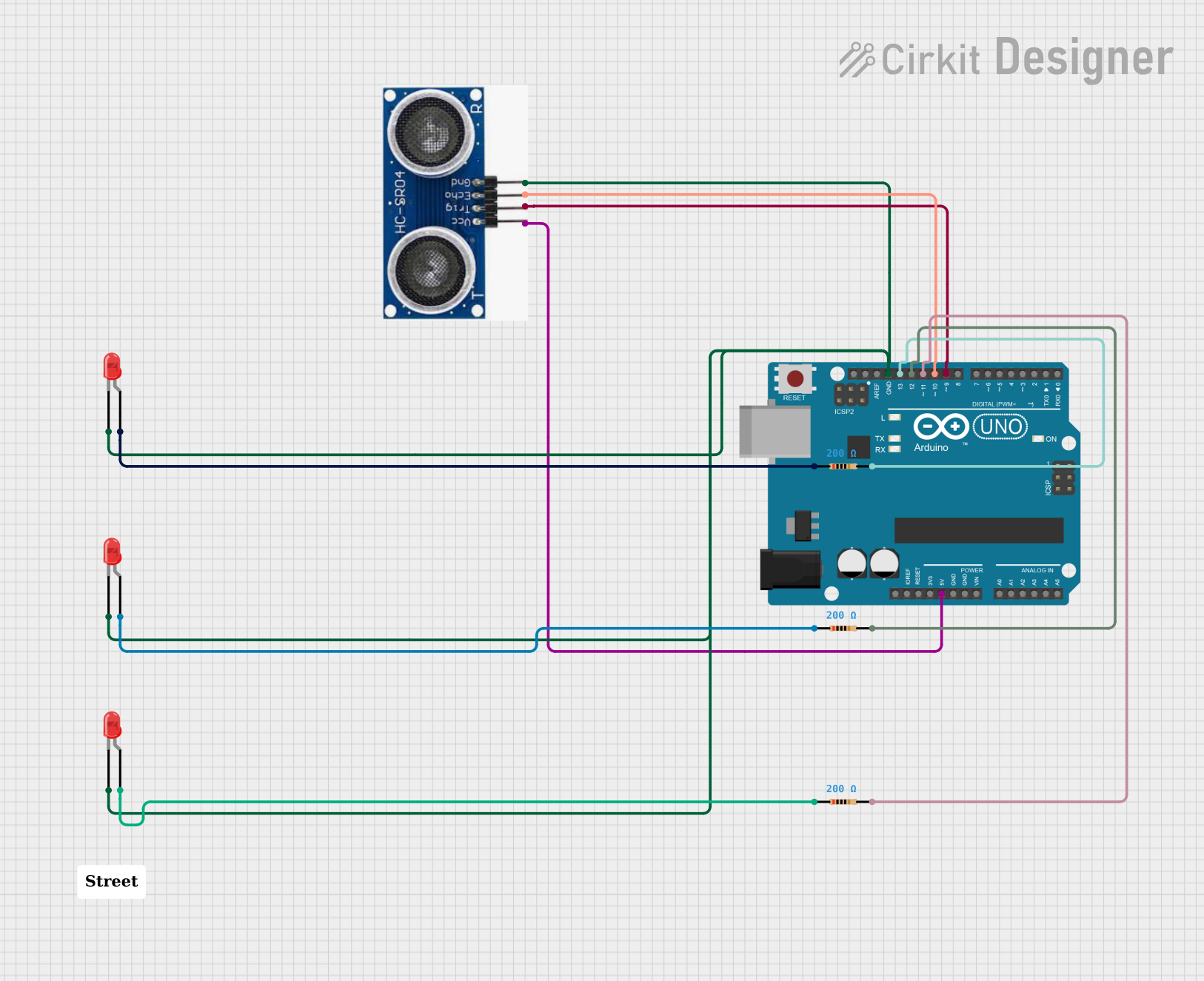
Circuit Documentation
Summary
This circuit is designed to utilize an Arduino UNO microcontroller to interface with an ultrasonic sensor and control three LEDs based on the distance measured by the sensor. The ultrasonic sensor is used to detect the presence of objects within a certain range, and if an object is detected within a predefined threshold distance, all three LEDs are turned on. Otherwise, the LEDs remain off. The circuit includes current-limiting resistors for each LED to ensure safe operation.
Component List
Arduino UNO
- Microcontroller board based on the ATmega328P
- It has 14 digital input/output pins, 6 analog inputs, a 16 MHz quartz crystal, a USB connection, a power jack, an ICSP header, and a reset button.
Ultrasonic Sensor
- A sensor that measures distance by emitting ultrasonic waves and detecting the time it takes for the waves to reflect back.
- It has four pins: Vcc, Trigger, Echo, and Gnd.
Resistor (200 Ohms)
- A passive two-terminal electrical component that implements electrical resistance as a circuit element.
- Three resistors are used in the circuit, each with a resistance of 200 Ohms.
LED: Two Pin (red)
- A light-emitting diode that emits red light when a forward current passes through it.
- Three individual red LEDs are used in the circuit.
Wiring Details
Arduino UNO
- 5V connected to the Vcc pin of the Ultrasonic sensor.
- GND connected to the Gnd pins of the Ultrasonic sensor and the cathodes of all three LEDs.
- D13 connected to one side of a 200 Ohm resistor, whose other side is connected to the anode of an LED.
- D12 connected to one side of a 200 Ohm resistor, whose other side is connected to the anode of another LED.
- D11 connected to one side of a 200 Ohm resistor, whose other side is connected to the anode of the third LED.
- D10 connected to the Echo pin of the Ultrasonic sensor.
- D9 connected to the Trigger pin of the Ultrasonic sensor.
Ultrasonic Sensor
- Vcc connected to the 5V output of the Arduino UNO.
- Trigger connected to pin D9 of the Arduino UNO.
- Echo connected to pin D10 of the Arduino UNO.
- Gnd connected to the GND pin of the Arduino UNO.
Resistor (200 Ohms)
- Three resistors are used, each connected in series with an LED between the anode of the LED and a digital output pin (D13, D12, D11) on the Arduino UNO.
LED: Two Pin (red)
- The cathode of each LED is connected to the GND pin of the Arduino UNO.
- The anode of each LED is connected to one side of a 200 Ohm resistor, whose other side is connected to a digital output pin (D13, D12, D11) on the Arduino UNO.
Documented Code
// Define pins
const int trigPin = 9;
const int echoPin = 10;
const int ledPin1 = 11;
const int ledPin2 = 12;
const int ledPin3 = 13;

// Define a threshold distance (e.g., 100 cm)
const int thresholdDistance = 100;

void setup() {
  // Initialize serial communication
  Serial.begin(9600);

  // Initialize pin modes
  pinMode(trigPin, OUTPUT);
  pinMode(echoPin, INPUT);
  pinMode(ledPin1, OUTPUT);
  pinMode(ledPin2, OUTPUT);
  pinMode(ledPin3, OUTPUT);
}

void loop() {
  // Clear the trigPin
  digitalWrite(trigPin, LOW);
  delayMicroseconds(2);

  // Set the trigPin HIGH for 10 microseconds
  digitalWrite(trigPin, HIGH);
  delayMicroseconds(10);
  digitalWrite(trigPin, LOW);

  // Read the echoPin
  long duration = pulseIn(echoPin, HIGH);

  // Calculate the distance
  int distance = duration * 0.034 / 2;

  // Print the distance to the Serial Monitor
  Serial.print("Distance: ");
  Serial.println(distance);

  // Turn all LEDs on if an object is within the threshold distance
  if (distance < thresholdDistance) {
    digitalWrite(ledPin1, HIGH);
    digitalWrite(ledPin2, HIGH);
    digitalWrite(ledPin3, HIGH);
  } else {
    digitalWrite(ledPin1, LOW);
    digitalWrite(ledPin2, LOW);
    digitalWrite(ledPin3, LOW);
  }

  // Short delay before the next loop
  delay(100);
}
This code is written for the Arduino UNO and is responsible for controlling the ultrasonic sensor and LEDs. It initializes the pins, measures the distance using the ultrasonic sensor, and turns the LEDs on or off based on the measured distance. The serial communication is used for debugging purposes to output the distance values to the Serial Monitor.