Cirkit Designer
Your all-in-one circuit design IDE
Home /
Project Documentation
ESP32-Based I2C Multiplexer Interface

Circuit Documentation
Summary of the Circuit
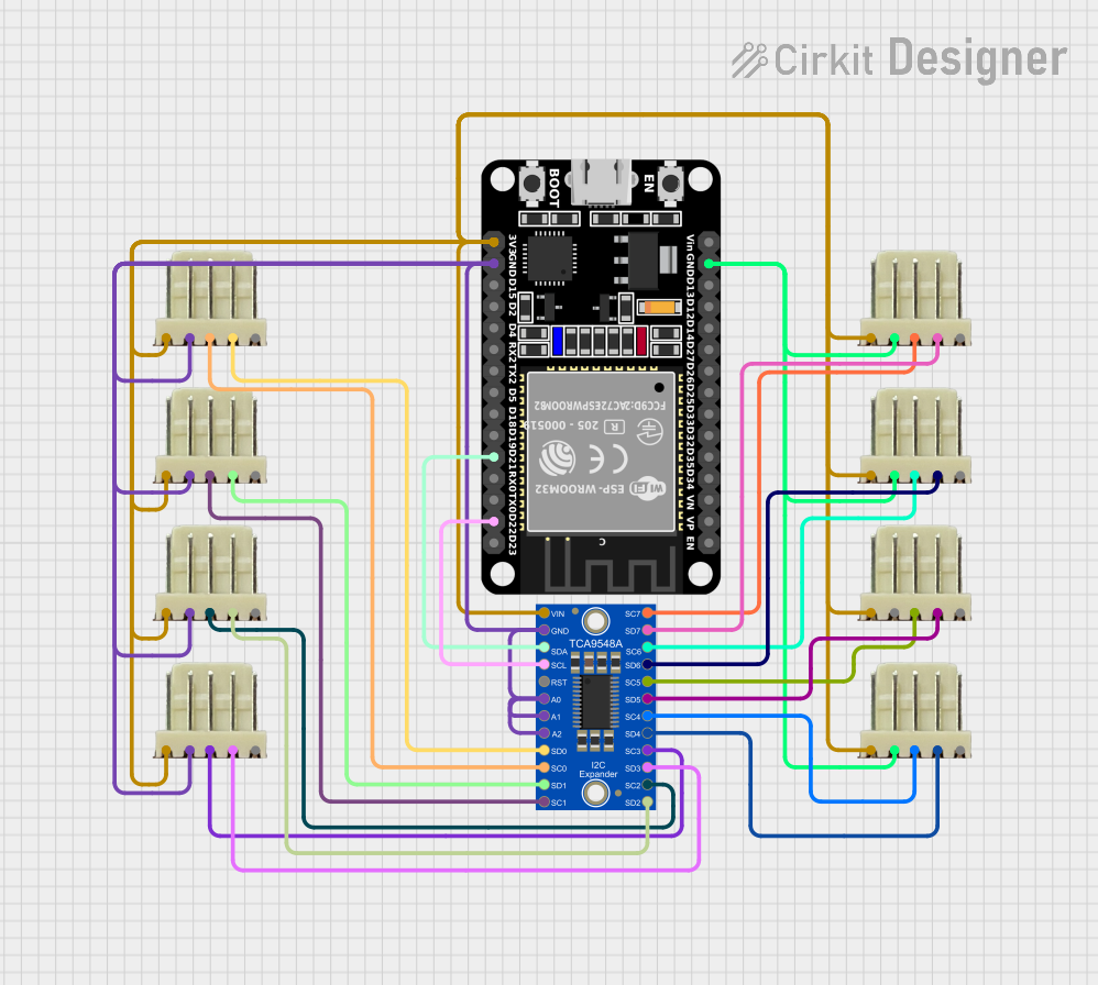
This circuit is designed around the ESP32 microcontroller, which serves as the central processing unit. The ESP32 is interfaced with an Adafruit TCA9548A I2C multiplexer, allowing for multiple I2C devices to be connected to the ESP32 via individual channels. Additionally, the circuit includes several 5-pin relimate connectors, which are likely used to connect I2C peripherals or other modules to the I2C bus through the multiplexer.
Component List
ESP32 (30 pin)
- Description: A 30-pin microcontroller with Wi-Fi and Bluetooth capabilities.
- Purpose: Acts as the central processing unit of the circuit, controlling the I2C multiplexer and interfacing with external devices through the relimate connectors.
Adafruit TCA9548A
- Description: An I2C multiplexer that allows for multiple I2C devices to be connected to a single I2C bus.
- Purpose: Expands the I2C capabilities of the ESP32 by providing 8 additional I2C buses.
5 pin relimate connectors
- Description: Connectors with 5 pins including power (VCC), ground (GND), I2C data (SDA), I2C clock (SCL), and an address line (ADDR).
- Purpose: These connectors are likely used to interface the ESP32 and the TCA9548A with external I2C devices or modules.
Wiring Details
ESP32 (30 pin)
- EN: Not connected in this documentation.
- VP, VN, D34-D27, D14, D12, D13, Vin, TX0, RX0, D19, D18, D5, TX2, RX2, D4, D2, D15: Not connected in this documentation.
- GND: Connected to the ground pins of all relimate connectors and the GND pin of the Adafruit TCA9548A.
- 3V3: Connected to the VCC pins of all relimate connectors and the VCC pin of the Adafruit TCA9548A.
- D22: Connected to the INPUTSCL pin of the Adafruit TCA9548A.
- D21: Connected to the INPUTSDA pin of the Adafruit TCA9548A.
Adafruit TCA9548A
- 2SDA, 2SCL: Connected to the SDA and SCL pins of a relimate connector.
- 3SDA, 3SCL: Connected to the SDA and SCL pins of a relimate connector.
- 4SDA, 4SCL: Connected to the SDA and SCL pins of a relimate connector.
- 5SDA, 5SCL: Connected to the SDA and SCL pins of a relimate connector.
- 6SDA, 6SCL: Connected to the SDA and SCL pins of a relimate connector.
- 7SDA, 7SCL: Connected to the SDA and SCL pins of a relimate connector.
- 0SDA, 0SCL: Connected to the SDA and SCL pins of a relimate connector.
- 1SDA, 1SCL: Connected to the SDA and SCL pins of a relimate connector.
- VCC: Connected to the 3V3 pin of the ESP32 and VCC pins of all relimate connectors.
- GND: Connected to the GND pin of the ESP32 and GND pins of all relimate connectors.
- RESET, A0, A1, A2: Connected to the GND pin of the ESP32 (assuming these are used to set the address of the TCA9548A to 0).
5 pin relimate connectors
- vcc: Connected to the 3V3 pin of the ESP32 and the VCC pin of the Adafruit TCA9548A.
- GND: Connected to the GND pin of the ESP32 and the GND pin of the Adafruit TCA9548A.
- SDA, SCL: Each pair connected to corresponding SDA and SCL pins on the Adafruit TCA9548A.
- ADDR: Not connected in this documentation.
Documented Code
No code has been provided for the microcontroller. Typically, the code would initialize the I2C bus, configure the TCA9548A, and handle communication with devices connected to the relimate connectors. Without the code, we cannot document the software aspect of this circuit.