
ESP32-Powered Battery-Operated Data Logger with Wi-Fi Connectivity
View and Edit Project In Cirkit Designer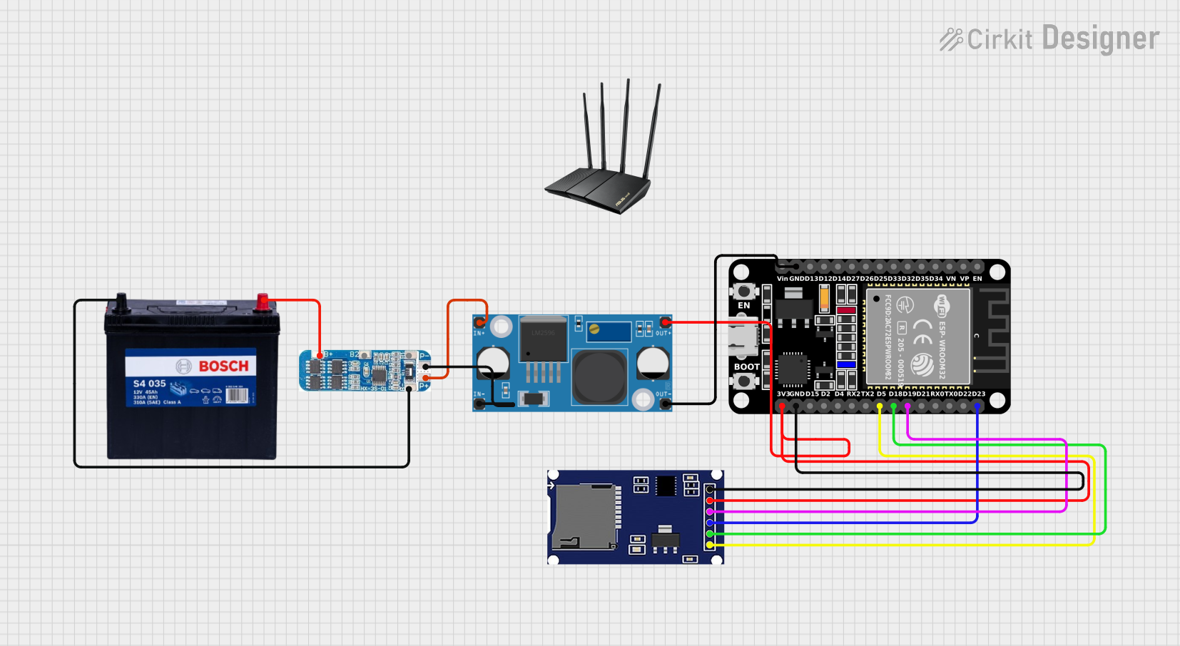
Circuit Documentation
Summary
This document provides a detailed overview of a circuit that includes an ESP32 microcontroller, a Battery Management System (BMS), a DC-DC Buck Converter, a 12V 200Ah Battery, an SD module, and a WiFi router. The circuit is designed to manage power distribution, data storage, and wireless communication.
Component List
ESP32 (30 pin)
- Description: A versatile microcontroller with built-in WiFi and Bluetooth capabilities.
- Pins: EN, VP, VN, D34, D35, D32, D33, D25, D26, D27, D14, D12, D13, GND, Vin, D23, D22, TX0, RX0, D21, D19, D18, D5, TX2, RX2, D4, D2, D15, 3V3
BMS
- Description: Battery Management System for monitoring and managing battery health.
- Pins: B+, B2, B1, B-, P+, P-
LM2956 Buck Converter DC-DC
- Description: A DC-DC buck converter for stepping down voltage.
- Pins: OUT+, OUT-, IN+, IN-
12V 200Ah Battery
- Description: A high-capacity battery for power storage.
- Pins: GND, 12V
SD Module
- Description: A module for interfacing with SD cards for data storage.
- Pins: CS, SCK, MOSI, MISO, VCC, GND
WiFi Router
- Description: A router for providing wireless internet connectivity.
- Pins: None
Wiring Details
ESP32 (30 pin)
3V3 is connected to:
- VCC of the SD Module
- OUT+ of the LM2956 Buck Converter DC-DC
GND is connected to:
- GND of the SD Module
- OUT- of the LM2956 Buck Converter DC-DC
D23 is connected to MOSI of the SD Module
D19 is connected to MISO of the SD Module
D18 is connected to SCK of the SD Module
D5 is connected to CS of the SD Module
BMS
- P+ is connected to IN+ of the LM2956 Buck Converter DC-DC
- P- is connected to IN- of the LM2956 Buck Converter DC-DC
- B+ is connected to 12V of the 12V 200Ah Battery
- B- is connected to GND of the 12V 200Ah Battery
LM2956 Buck Converter DC-DC
OUT+ is connected to:
- 3V3 of the ESP32 (30 pin)
- VCC of the SD Module
OUT- is connected to GND of the ESP32 (30 pin)
IN+ is connected to P+ of the BMS
IN- is connected to P- of the BMS
12V 200Ah Battery
- 12V is connected to B+ of the BMS
- GND is connected to B- of the BMS
SD Module
- VCC is connected to 3V3 of the ESP32 (30 pin)
- GND is connected to GND of the ESP32 (30 pin)
- MOSI is connected to D23 of the ESP32 (30 pin)
- MISO is connected to D19 of the ESP32 (30 pin)
- SCK is connected to D18 of the ESP32 (30 pin)
- CS is connected to D5 of the ESP32 (30 pin)
WiFi Router
- No electrical connections specified.
Code
No code is provided for this circuit.
This document provides a comprehensive overview of the circuit, including a summary, component list, wiring details, and code documentation. Each section is designed to offer clear and concise information for understanding and replicating the circuit.