Cirkit Designer
Your all-in-one circuit design IDE
Home /
Project Documentation
Arduino Nano RFID-Based Time Tracking System with LCD Display and Relay Control
Circuit Documentation
Summary
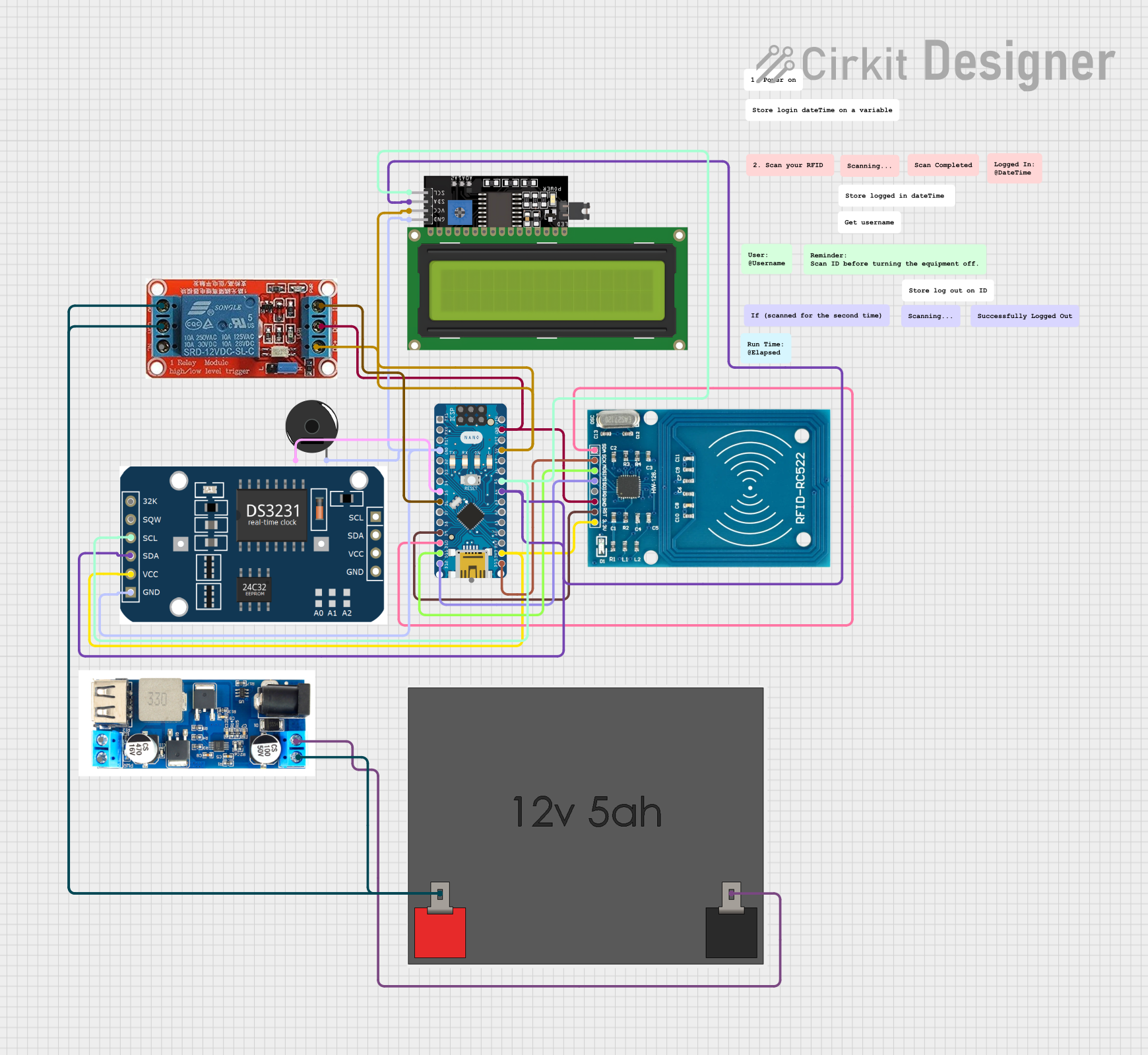
This circuit is designed to manage an RFID-based access control system. It includes an Arduino Nano microcontroller, an RFID reader, an LCD display, a real-time clock (RTC) module, a piezo buzzer, a relay, and a step-down voltage regulator. The system reads RFID tags, logs the time of access, and displays the information on an LCD. It also controls a relay to manage power to an external device and uses a buzzer for audio feedback.
Component List
Arduino Nano
- Description: A small, complete, and breadboard-friendly board based on the ATmega328P.
- Pins: D1/TX, D0/RX, RESET, GND, D2, D3, D4, D5, D6, D7, D8, D9, D10, D11/MOSI, D12/MISO, VIN, 5V, A7, A6, A5, A4, A3, A2, A1, A0, AREF, 3V3, D13/SCK
RFID-RC522
- Description: A low-cost RFID reader module that uses the SPI protocol.
- Pins: VCC (3.3V), RST, GND, IRQ, MISO, MOSI, SCK, SDA
LCD Display 16x4 I2C
- Description: A 16x4 character LCD display with I2C interface.
- Pins: SCL, SDA, VCC, GND
rtc MODULE
- Description: A real-time clock module for keeping track of time.
- Pins: 32k, SQW, SCL, SDA, VCC, GND
Piezo Buzzer
- Description: A simple piezoelectric buzzer for audio feedback.
- Pins: pin 1, pin 2
12v Relay
- Description: A relay module for switching high voltage devices.
- Pins: NO, COM, NC, IN, DC-, DC+
STEP DOWN XY 3606
- Description: A step-down voltage regulator for converting 12V to 5V.
- Pins: 5V, GND, VIN+, VIN-
12v5ah Battery
- Description: A 12V 5Ah battery for powering the circuit.
- Pins: 12v +, 12v -
Wiring Details
Arduino Nano
- GND: Connected to GND of Piezo Buzzer, rtc MODULE, LCD Display 16x4 I2C, and 12v Relay.
- D5: Connected to pin 1 of Piezo Buzzer.
- D6: Connected to IN of 12v Relay.
- D9: Connected to RST of RFID-RC522.
- D10: Connected to SDA of RFID-RC522.
- D11/MOSI: Connected to MOSI of RFID-RC522.
- D12/MISO: Connected to MISO of RFID-RC522.
- 5V: Connected to VCC of LCD Display 16x4 I2C and DC+ of 12v Relay.
- A5: Connected to SCL of rtc MODULE and LCD Display 16x4 I2C.
- A4: Connected to SDA of rtc MODULE and LCD Display 16x4 I2C.
- 3V3: Connected to VCC of rtc MODULE and VCC (3.3V) of RFID-RC522.
- D13/SCK: Connected to SCK of RFID-RC522.
RFID-RC522
- VCC (3.3V): Connected to 3V3 of Arduino Nano.
- RST: Connected to D9 of Arduino Nano.
- GND: Connected to GND of Arduino Nano.
- MISO: Connected to D12/MISO of Arduino Nano.
- MOSI: Connected to D11/MOSI of Arduino Nano.
- SCK: Connected to D13/SCK of Arduino Nano.
- SDA: Connected to D10 of Arduino Nano.
LCD Display 16x4 I2C
- SCL: Connected to A5 of Arduino Nano and SCL of rtc MODULE.
- SDA: Connected to A4 of Arduino Nano and SDA of rtc MODULE.
- VCC: Connected to 5V of Arduino Nano.
- GND: Connected to GND of Arduino Nano.
rtc MODULE
- SCL: Connected to A5 of Arduino Nano and SCL of LCD Display 16x4 I2C.
- SDA: Connected to A4 of Arduino Nano and SDA of LCD Display 16x4 I2C.
- VCC: Connected to 3V3 of Arduino Nano.
- GND: Connected to GND of Arduino Nano.
Piezo Buzzer
- pin 1: Connected to D5 of Arduino Nano.
- pin 2: Connected to GND of Arduino Nano.
12v Relay
- IN: Connected to D6 of Arduino Nano.
- DC-: Connected to GND of Arduino Nano.
- DC+: Connected to 5V of Arduino Nano.
- NO: Connected to COM of 12v Relay.
- COM: Connected to NO of 12v Relay.
- NC: Not connected.
STEP DOWN XY 3606
- VIN+: Connected to 12v + of 12v5ah Battery.
- VIN-: Connected to 12v - of 12v5ah Battery.
12v5ah Battery
- 12v +: Connected to VIN+ of STEP DOWN XY 3606.
- 12v -: Connected to VIN- of STEP DOWN XY 3606.
Code Documentation
#include <Wire.h>
#include <RTClib.h>
#include <LiquidCrystal_I2C.h>

// Initialize the LCD display with I2C address 0x27 and size 16x2
LiquidCrystal_I2C lcd(0x27, 16, 2);

// Initialize the RTC module
RTC_DS3231 rtc;

// Variables to store login and logout times
DateTime loggedIn;
DateTime loggedOut;

// Variable to store the period (AM/PM)
String period = "AM";

// Pin definitions
const byte BUZZER_PIN = 5;
const byte BUTTON_PIN = 3;
const byte RELAY_PIN = 6; // Relay connected to D6

// Variables to track button state
byte lastState = LOW;  // Previous state of the button
int currentState;      // Current state of the button

void setup() {
  // Start the I2C communication
  Wire.begin();

  // Set pin modes
  pinMode(BUZZER_PIN, OUTPUT);
  pinMode(BUTTON_PIN, INPUT_PULLUP);
  pinMode(RELAY_PIN, OUTPUT);
  digitalWrite(RELAY_PIN, LOW); // Ensure relay is off initially

  // Initialize serial communication at 9600 bits per second
  Serial.begin(9600);

  // Initialize the LCD display
  lcd.init();
  lcd.backlight();

  // Initialize the RTC module
  if (!rtc.begin()) {
    Serial.print("Couldn't find RTC");
    Serial.flush();
    while (1);
  }

  // Check if the RTC lost power and set the time if necessary
  if (rtc.lostPower()) {
    Serial.println("RTC lost power, let's set the time!");
    rtc.adjust(DateTime(F(__DATE__), F(__TIME__)));
  }

  // Display the login time on the LCD
  lcd.clear();
  lcd.print("Logged In:");
  loggedIn = rtc.now();
  displayTime(loggedIn);
}

void loop() {
  // Read the state of the button
  currentState = digitalRead(BUTTON_PIN);

  // Check for button press (transition from HIGH to LOW)
  if (lastState == HIGH && currentState == LOW) {
    // Sound the buzzer
    tone(BUZZER_PIN, 2000); // Send a 2kHz sound signal
    delay(500);             // for 0.5 seconds
    noTone(BUZZER_PIN);     // Stop the tone

    // Display the logout time on the LCD
    lcd.clear();
    lcd.print("Logged Out:");
    loggedOut = rtc.now();
    displayTime(loggedOut);

    delay(3000);
    lcd.clear();

    // Calculate and display the elapsed time
    long elapsedSeconds = loggedOut.unixtime() - loggedIn.unixtime();
    int elapsedHours = elapsedSeconds / 3600;
    int elapsedMinutes = (elapsedSeconds % 3600) / 60;
    int elapsedSecondsRemaining = elapsedSeconds % 60;

    lcd.print("Elapsed time:");
    lcd.setCursor(0, 1);
    lcd.print(elapsedHours);
    lcd.print("h ");
    lcd.print(elapsedMinutes);
    lcd.print("m ");
    lcd.print(elapsedSecondsRemaining);
    lcd.print("s");

    delay(5000);
    lcd.clear();

    // Turn on the relay