
Arduino Nano-Based Health Monitoring System with Wi-Fi and GPS
View and Edit Project In Cirkit Designer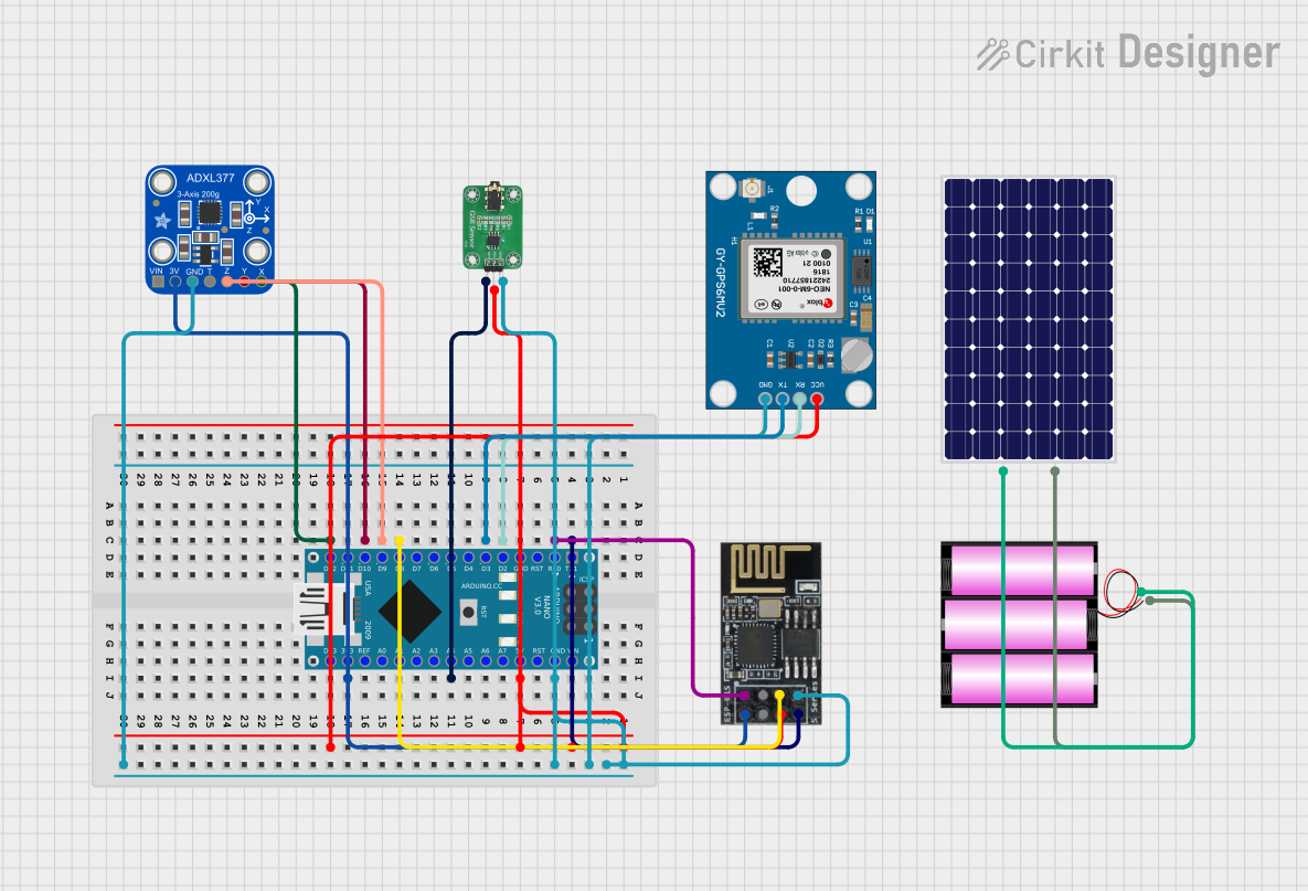
Circuit Documentation
Summary
This document provides a detailed overview of a circuit that integrates various sensors and modules with an Arduino Nano microcontroller. The circuit includes a GSR sensor, an accelerometer (Adafruit ADXL377), a GPS module (Neo 6M), and a WiFi module (ESP8266-01). The circuit is powered by a combination of a solar panel and a 12V battery.
Component List
Arduino Nano
- Description: A small, complete, and breadboard-friendly board based on the ATmega328P.
- Pins: D1/TX, D0/RX, RESET, GND, D2, D3, D4, D5, D6, D7, D8, D9, D10, D11/MOSI, D12/MISO, VIN, 5V, A7, A6, A5, A4, A3, A2, A1, A0, AREF, 3V3, D13/SCK
GSR Sensor
- Description: A sensor used to measure the electrical conductance of the skin, which varies with its moisture level.
- Pins: GND, VCC, OUT
Adafruit ADXL377
- Description: A high-g accelerometer that measures acceleration in three axes.
- Pins: VIN, 3.3V, GND, SELFTEST, ZOUT, YOUT, XOUT
Neo 6M GPS Module
- Description: A GPS module used for obtaining geographical location data.
- Pins: GND, TX, RX, VCC
WiFi Module ESP8266-01
- Description: A self-contained WiFi networking solution that can be used to connect to the internet.
- Pins: RX, GPIO0, GPIO2, GND, +3V3, Reset, CH-PD Chip power down, TX
Solar Panel
- Description: A device that converts sunlight into electrical energy.
- Pins: +, -
Battery 12V
- Description: A 12V battery used to store electrical energy.
- Pins: +, -
Wiring Details
Arduino Nano
- 5V: Connected to VCC of GSR Sensor, VCC of Neo 6M GPS Module, and CH-PD Chip power down of WiFi Module ESP8266-01
- GND: Connected to GND of GSR Sensor, GND of Neo 6M GPS Module, GND of Adafruit ADXL377, and GND of WiFi Module ESP8266-01
- D1/TX: Connected to TX of WiFi Module ESP8266-01
- D0/RX: Connected to RX of WiFi Module ESP8266-01
- D2: Connected to RX of Neo 6M GPS Module
- D3: Connected to TX of Neo 6M GPS Module
- A4: Connected to OUT of GSR Sensor
- D8: Connected to GPIO2 of WiFi Module ESP8266-01
- D9: Connected to ZOUT of Adafruit ADXL377
- D10: Connected to YOUT of Adafruit ADXL377
- 3V3: Connected to 3.3V of Adafruit ADXL377 and +3V3 of WiFi Module ESP8266-01
- D12/MISO: Connected to XOUT of Adafruit ADXL377
GSR Sensor
- GND: Connected to GND of Arduino Nano
- VCC: Connected to 5V of Arduino Nano
- OUT: Connected to A4 of Arduino Nano
Adafruit ADXL377
- GND: Connected to GND of Arduino Nano
- 3.3V: Connected to 3V3 of Arduino Nano
- ZOUT: Connected to D9 of Arduino Nano
- YOUT: Connected to D10 of Arduino Nano
- XOUT: Connected to D12/MISO of Arduino Nano
Neo 6M GPS Module
- GND: Connected to GND of Arduino Nano
- VCC: Connected to 5V of Arduino Nano
- RX: Connected to D2 of Arduino Nano
- TX: Connected to D3 of Arduino Nano
WiFi Module ESP8266-01
- GND: Connected to GND of Arduino Nano
- +3V3: Connected to 3V3 of Arduino Nano
- CH-PD Chip power down: Connected to 5V of Arduino Nano
- TX: Connected to D1/TX of Arduino Nano
- RX: Connected to D0/RX of Arduino Nano
- GPIO2: Connected to D8 of Arduino Nano
Solar Panel
- +: Connected to + of Battery 12V
- -: Connected to - of Battery 12V
Battery 12V
- +: Connected to + of Solar Panel
- -: Connected to - of Solar Panel
Documented Code
Arduino Nano Code (sketch.ino)
void setup() {
  // put your setup code here, to run once:

}

void loop() {
  // put your main code here, to run repeatedly:

}
Additional Documentation (documentation.txt)