
ESP8266 NodeMCU-Based RFID and Fingerprint Authentication System
View and Edit Project In Cirkit Designer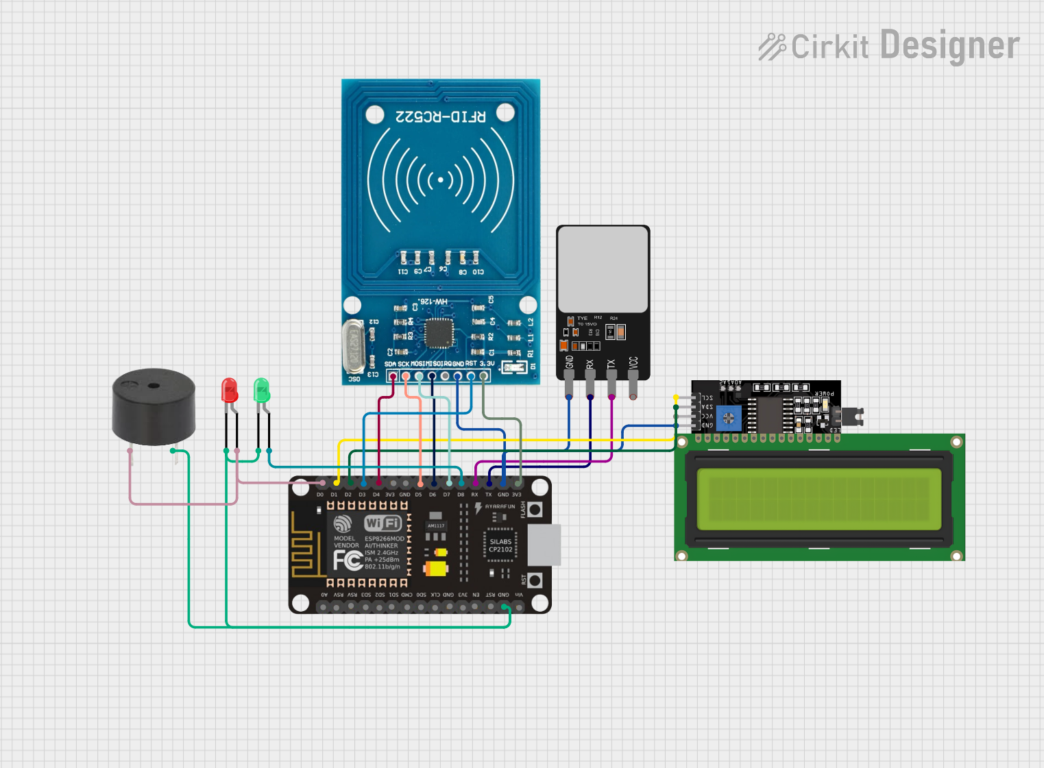
Circuit Documentation
Summary
The circuit in question is designed around the ESP8266 NodeMCU microcontroller, which serves as the central processing unit. The circuit includes a variety of peripherals, including a buzzer, red and green LEDs, an RFID-RC522 module, a fingerprint scanner, and an LCD Display with I2C interface. The purpose of the circuit is to create a security access system that uses RFID and fingerprint authentication to grant or deny access, with visual feedback provided by the LEDs and the LCD display, and auditory feedback provided by the buzzer.
Component List
ESP8266 NodeMCU
- Microcontroller with WiFi capability.
- Provides GPIO pins for interfacing with other components.
Buzzer
- An audible signaling device.
LED: Two Pin (red)
- A red light-emitting diode for visual indication.
LED: Two Pin (green)
- A green light-emitting diode for visual indication.
RFID-RC522
- An RFID reader/writer module for contactless communication using radio frequencies.
Fingerprint Scanner
- A biometric sensor for identifying individuals based on their fingerprints.
LCD Display 16x4 I2C
- An alphanumeric liquid crystal display with an I2C interface for displaying text.
Wiring Details
ESP8266 NodeMCU
D0connected to the anode of the red LED and the PIN of the buzzer.D1connected to the SCL pin of the LCD Display.D2connected to the SDA pin of the LCD Display.D3connected to the RST pin of the RFID-RC522.D4connected to the SDA pin of the RFID-RC522.D5connected to the SCK pin of the RFID-RC522.D6connected to the MISO pin of the RFID-RC522.D7connected to the MOSI pin of the RFID-RC522.D8connected to the anode of the green LED.RXconnected to the TX pin of the Fingerprint Scanner.TXconnected to the RX pin of the Fingerprint Scanner.GNDconnected to the GND pins of all components.3V3connected to the VCC (3.3V) pin of the RFID-RC522.
Buzzer
PINconnected toD0of the ESP8266 NodeMCU.GNDconnected to the common ground.
LED: Two Pin (red)
anodeconnected toD0of the ESP8266 NodeMCU.cathodeconnected to the common ground.
LED: Two Pin (green)
anodeconnected toD8of the ESP8266 NodeMCU.cathodeconnected to the common ground.
RFID-RC522
VCC (3.3V)connected to3V3of the ESP8266 NodeMCU.RSTconnected toD3of the ESP8266 NodeMCU.GNDconnected to the common ground.IRQnot connected.MISOconnected toD6of the ESP8266 NodeMCU.MOSIconnected toD7of the ESP8266 NodeMCU.SCKconnected toD5of the ESP8266 NodeMCU.SDAconnected toD4of the ESP8266 NodeMCU.
Fingerprint Scanner
VCCnot connected (assumed to be powered externally).TXconnected toRXof the ESP8266 NodeMCU.RXconnected toTXof the ESP8266 NodeMCU.GNDconnected to the common ground.
LCD Display 16x4 I2C
SCLconnected toD1of the ESP8266 NodeMCU.SDAconnected toD2of the ESP8266 NodeMCU.VCCnot connected (assumed to be powered externally).GNDconnected to the common ground.
Documented Code
#include <SPI.h>
#include <MFRC522.h>
#include <Adafruit_Fingerprint.h>
#include <Wire.h>
#include <LiquidCrystal_I2C.h>
#include <ESP8266WiFi.h>
#include <ESP8266HTTPClient.h>
#include <WiFiClient.h>
#include <time.h>  // Include time library for NTP

// Define pins for RFID and peripherals
#define SS_PIN D4
#define RST_PIN D3
#define BUZZER_PIN D8
#define led D0
#define LCD_ADDRESS 0x27 // Define I2C address for LCD (typically 0x27 or 0x3F)

// Initialize the I2C LCD with address 0x27 and 20 columns x 4 rows
LiquidCrystal_I2C lcd(LCD_ADDRESS, 20, 4);

MFRC522 mfrc522(SS_PIN, RST_PIN);  // Create MFRC522 instance
Adafruit_Fingerprint finger = Adafruit_Fingerprint(&Serial);  // Fingerprint sensor setup using hardware serial

// List of allowed RFID card UIDs with their associated fingerprint IDs, type, name, PC brand, and serial number
struct AllowedCard {
  byte uid[8];
  int type; // 0 = Student, 1 = Staff
  uint16_t fingerprintID; // Associated fingerprint ID
  String fullName;
  String pcBrand;
  String serialNumber;
  String regNumber;  // Registration number (for students)
};

AllowedCard allowedCards[] = {
  {{0x73, 0xB5, 0xAE, 0x1A}, 0, 1, "Leon", "Dell", "SN123456", "REG123"},  // Student
  {{0xB3, 0xD0, 0x35, 0x42}, 1, 2, "Ngabo Robert", "HP", "SN654321", ""},   // Staff
  {{0x57, 0xC3, 0x5E, 0x86}, 0, 3, "Selemani", "Lenovo", "SN789012", "REG456"}  // Student
};

// WiFi credentials
const char* ssid = "Leon";
const char* password = "1234567890";
const char* serverUrl = "http://192.168.84.185/yourFolderName/uploadData.php";  // Replace with your local server address

// NTP Server
const char* ntpServer = "pool.ntp.org";
const long gmtOffset_sec = 3600;  // Offset for your timezone, e.g., +1 hour (GMT+1)
const int daylightOffset_sec = 3600;  // Daylight saving offset (if applicable)

// Variable to track Sign-In/Sign-Out
String signStatus = "Sign-In";

void setup() {
  Serial.begin(57600);
  finger.begin(57600); // Start fingerprint sensor
  SPI.begin();        // Init SPI bus
  mfrc522.PCD_Init(); // Init MFRC522

  pinMode(BUZZER_PIN, OUTPUT);
  lcd.begin();
  lcd.backlight(); // Turn on the backlight
  lcd.setCursor(0, 0);
  lcd.print("RFID Reader Ready");

  if (finger.verifyPassword()) {
    lcd.setCursor(0, 1);
    lcd.print("Fingerprint Ready");
  } else {
    lcd.setCursor(0, 1);
    lcd.print("Fingerprint Error");
    while (1);
  }

  connectToWiFi();
  configTime(gmtOffset_sec, daylightOffset_sec, ntpServer);  // Initialize NTP time synchronization

  Serial.println("RFID Reader Initialized.");
  Serial.println("Tap your card to begin...");
}

void loop() {
  // Rest of the code...
}

// Additional functions...
The code provided is a partial listing, focusing on the setup and initialization of the components. It includes the setup of the RFID reader, fingerprint scanner, LCD display, and WiFi connection. The loop function and additional utility functions are implied to handle the main logic of the access control system, including reading RFID tags, verifying fingerprints, and communicating with a server.