Cirkit Designer
Your all-in-one circuit design IDE
Home /
Project Documentation
Arduino UNO Controlled RGB LED Indicator
Circuit Documentation
Summary of the Circuit
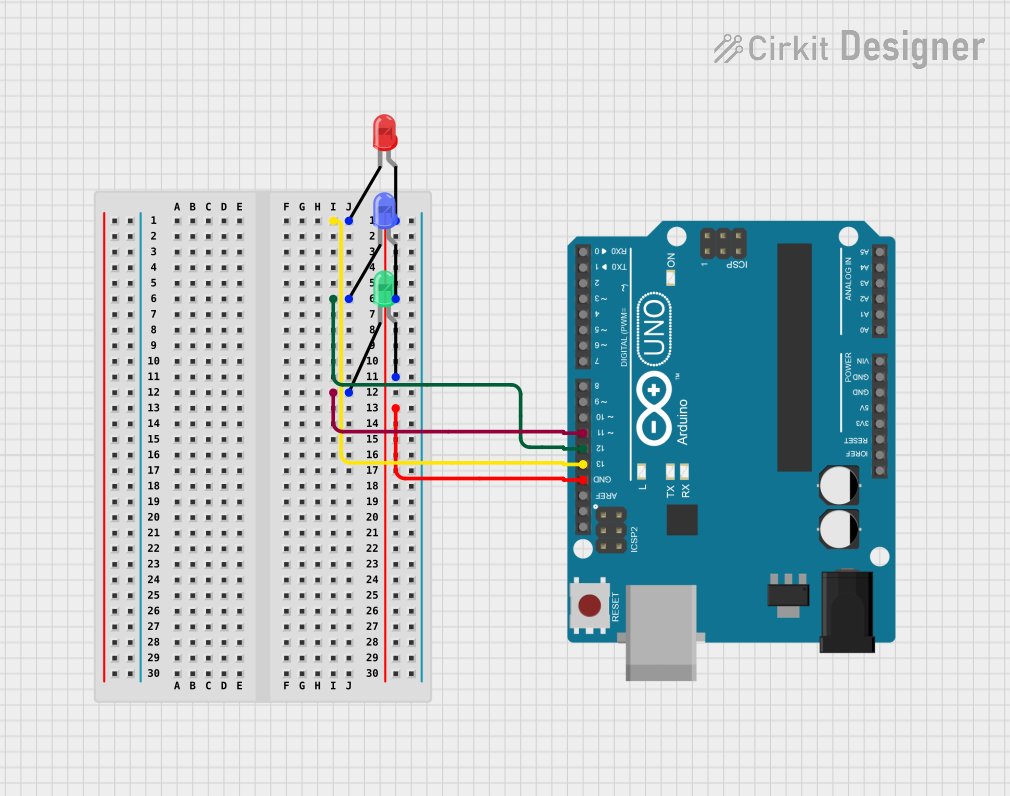
This circuit consists of an Arduino UNO microcontroller board and three LEDs: one red, one green, and one blue. Each LED is connected to a digital output pin on the Arduino UNO, allowing the microcontroller to control the state of each LED (on or off). The cathodes of all LEDs are connected to individual digital pins, while their anodes are tied together and connected to the ground (GND) pin of the Arduino UNO.
Component List
Arduino UNO
- Description: A microcontroller board based on the ATmega328P.
- Pins Used:
IOREFReset3.3V5VGNDVinA0toA5SCLSDAAREFD13toD0
LED: Two Pin (red)
- Description: A red light-emitting diode.
- Pins:
cathodeanode
LED: Two Pin (green)
- Description: A green light-emitting diode.
- Pins:
cathodeanode
LED: Two Pin (blue)
- Description: A blue light-emitting diode.
- Pins:
cathodeanode
Wiring Details
Arduino UNO
- D13: Connected to the cathode of the red LED.
- D12: Connected to the cathode of the blue LED.
- D11: Connected to the cathode of the green LED.
- GND: Connected to the anodes of all three LEDs (common ground).
LED: Two Pin (red)
- Cathode: Connected to Arduino UNO pin D13.
- Anode: Connected to Arduino UNO GND.
LED: Two Pin (green)
- Cathode: Connected to Arduino UNO pin D11.
- Anode: Connected to Arduino UNO GND.
LED: Two Pin (blue)
- Cathode: Connected to Arduino UNO pin D12.
- Anode: Connected to Arduino UNO GND.
Documented Code
Arduino UNO Code (sketch.ino)
void setup() {
  // put your setup code here, to run once:

}

void loop() {
  // put your main code here, to run repeatedly:

}
Note: The provided code is a template and does not include any logic to control the LEDs. To control the LEDs, code should be added to the setup() function to initialize the pins as outputs and to the loop() function to turn the LEDs on or off.