Cirkit Designer
Your all-in-one circuit design IDE
Home /
Project Documentation
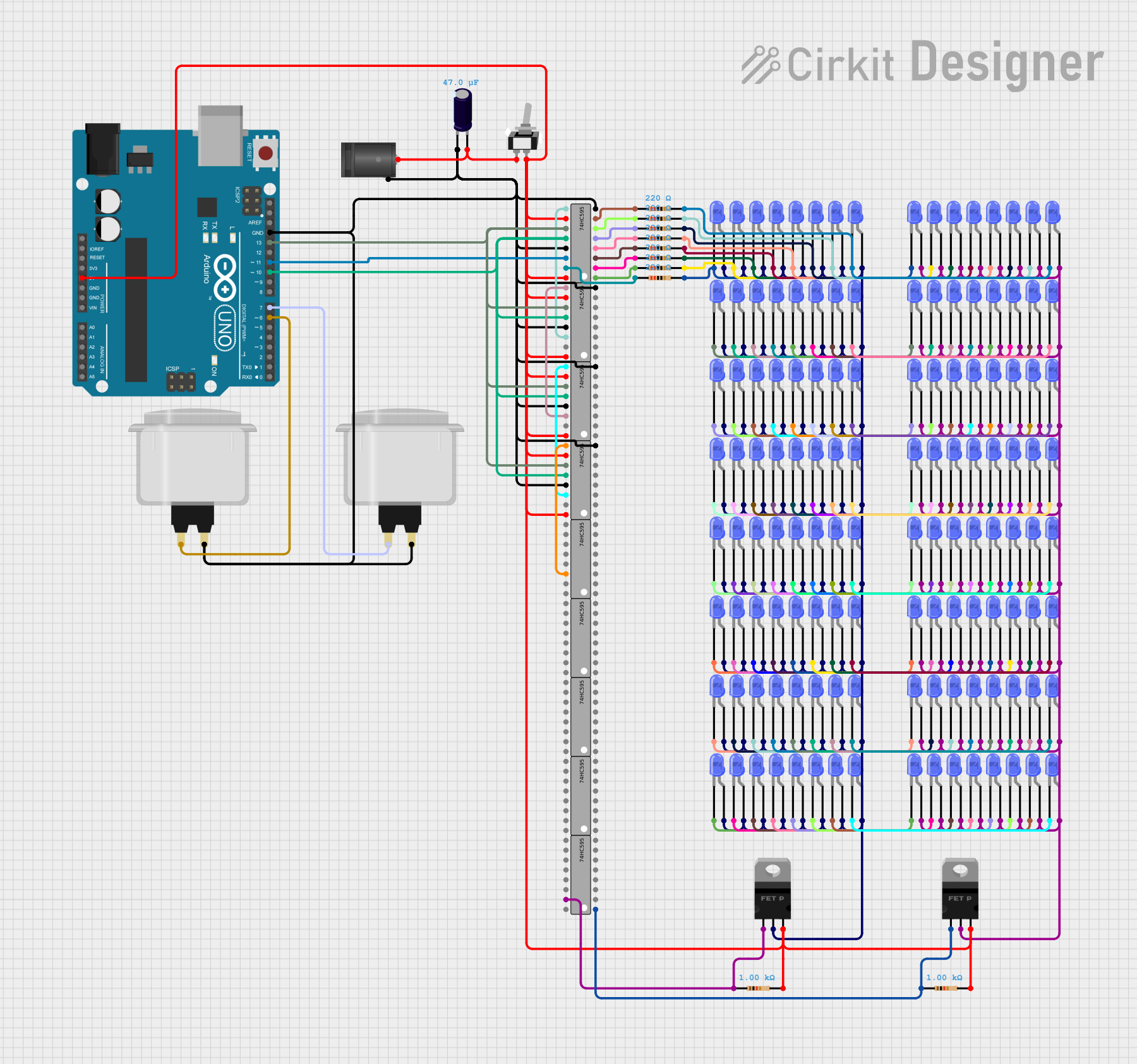
Arduino UNO Controlled LED Matrix with 74HC595 Shift Registers
Circuit Documentation
Summary
This circuit is designed to control multiple blue LEDs using an Arduino UNO and several 74HC595 shift registers. The circuit also includes pMOS transistors, resistors, capacitors, and arcade buttons. The Arduino UNO is programmed to control the LEDs through the shift registers, allowing for efficient use of I/O pins.
Component List
LED: Two Pin (blue)
- Description: A blue LED with two pins: cathode and anode.
- Pins: cathode, anode
2.1mm DC Barrel Jack
- Description: A standard DC barrel jack for power input.
- Pins: switch, sleeve, center
Arduino UNO
- Description: A microcontroller board based on the ATmega328P.
- Pins: UNUSED, IOREF, Reset, 3.3V, 5V, GND, Vin, A0, A1, A2, A3, A4, A5, SCL, SDA, AREF, D13, D12, D11, D10, D9, D8, D7, D6, D5, D4, D3, D2, D1, D0
pMOS Transistor (MOSFET)
- Description: A p-channel MOSFET used for switching.
- Pins: gate, drain, source
Toggle Switch SPST
- Description: A single-pole single-throw toggle switch.
- Pins: L1, COM
Electrolytic Capacitor
- Description: A capacitor with a capacitance of 0.000047 Farads.
- Pins: -, +
Resistor
- Description: A resistor with various resistance values.
- Pins: pin1, pin2
Arcade Button (white)
- Description: A white arcade button.
- Pins: no name yet
74HC595
- Description: An 8-bit shift register.
- Pins: Q1, Q2, Q3, Q4, Q5, Q6, Q7, GND, VCC, Q0, DS (DATA), OE (Enable), ST_CP (RCLK), SH_CP (SRCLK), MR (SRCLR), Q7' (QH)
Wiring Details
LED: Two Pin (blue)
- Cathode: Connected to the cathode of another LED and to the pin2 of a resistor.
- Anode: Connected to the drain of a pMOS transistor and to the anode of other LEDs.
2.1mm DC Barrel Jack
- Switch: Not connected.
- Sleeve: Connected to the GND of the Arduino UNO and other components.
- Center: Connected to the L1 of the toggle switch and the positive pin of the electrolytic capacitor.
Arduino UNO
- 5V: Connected to the VCC of the 74HC595 shift registers and the source of the pMOS transistors.
- GND: Connected to the GND of the 74HC595 shift registers, the sleeve of the DC barrel jack, and other components.
- D13: Connected to the SH_CP (SRCLK) of the 74HC595 shift registers.
- D11: Connected to the DS (DATA) of the first 74HC595 shift register.
- D10: Connected to the ST_CP (RCLK) of the 74HC595 shift registers.
- D7: Connected to the arcade button.
- D6: Connected to another arcade button.
pMOS Transistor (MOSFET)
- Gate: Connected to the Q0 of a 74HC595 shift register and to the pin1 of a resistor.
- Drain: Connected to the anode of multiple LEDs.
- Source: Connected to the 5V of the Arduino UNO.
Toggle Switch SPST
- L1: Connected to the center pin of the DC barrel jack and the positive pin of the electrolytic capacitor.
- COM: Connected to the source of the pMOS transistors and the VCC of the 74HC595 shift registers.
Electrolytic Capacitor
- Positive (+): Connected to the L1 of the toggle switch and the center pin of the DC barrel jack.
- Negative (-): Connected to the GND of the Arduino UNO and other components.
Resistor
- Pin1: Connected to the Q0-Q7 of the 74HC595 shift registers.
- Pin2: Connected to the cathode of the LEDs.
Arcade Button (white)
- No name yet: Connected to the OE (Enable) of the 74HC595 shift registers and the GND of the Arduino UNO.
74HC595
- VCC: Connected to the 5V of the Arduino UNO.
- GND: Connected to the GND of the Arduino UNO.
- SH_CP (SRCLK): Connected to the D13 of the Arduino UNO.
- DS (DATA): Connected to the D11 of the Arduino UNO.
- ST_CP (RCLK): Connected to the D10 of the Arduino UNO.
- MR (SRCLR): Connected to the source of the pMOS transistors and the 5V of the Arduino UNO.
- OE (Enable): Connected to the arcade button and the GND of the Arduino UNO.
- Q0-Q7: Connected to the gate of the pMOS transistors and the pin1 of the resistors.
- Q7' (QH): Connected to the DS (DATA) of the next 74HC595 shift register.
Documented Code
sketch.ino
void setup() {
  // put your setup code here, to run once:

}

void loop() {
  // put your main code here, to run repeatedly:

}
documentation.txt
This documentation provides a comprehensive overview of the circuit, including a summary, component list, wiring details, and documented code.