Cirkit Designer
Your all-in-one circuit design IDE
Home /
Project Documentation
STM32 and ESP8266 Nodemcu Based Smart Lock System with LCD and Keypad
Circuit Documentation
Summary
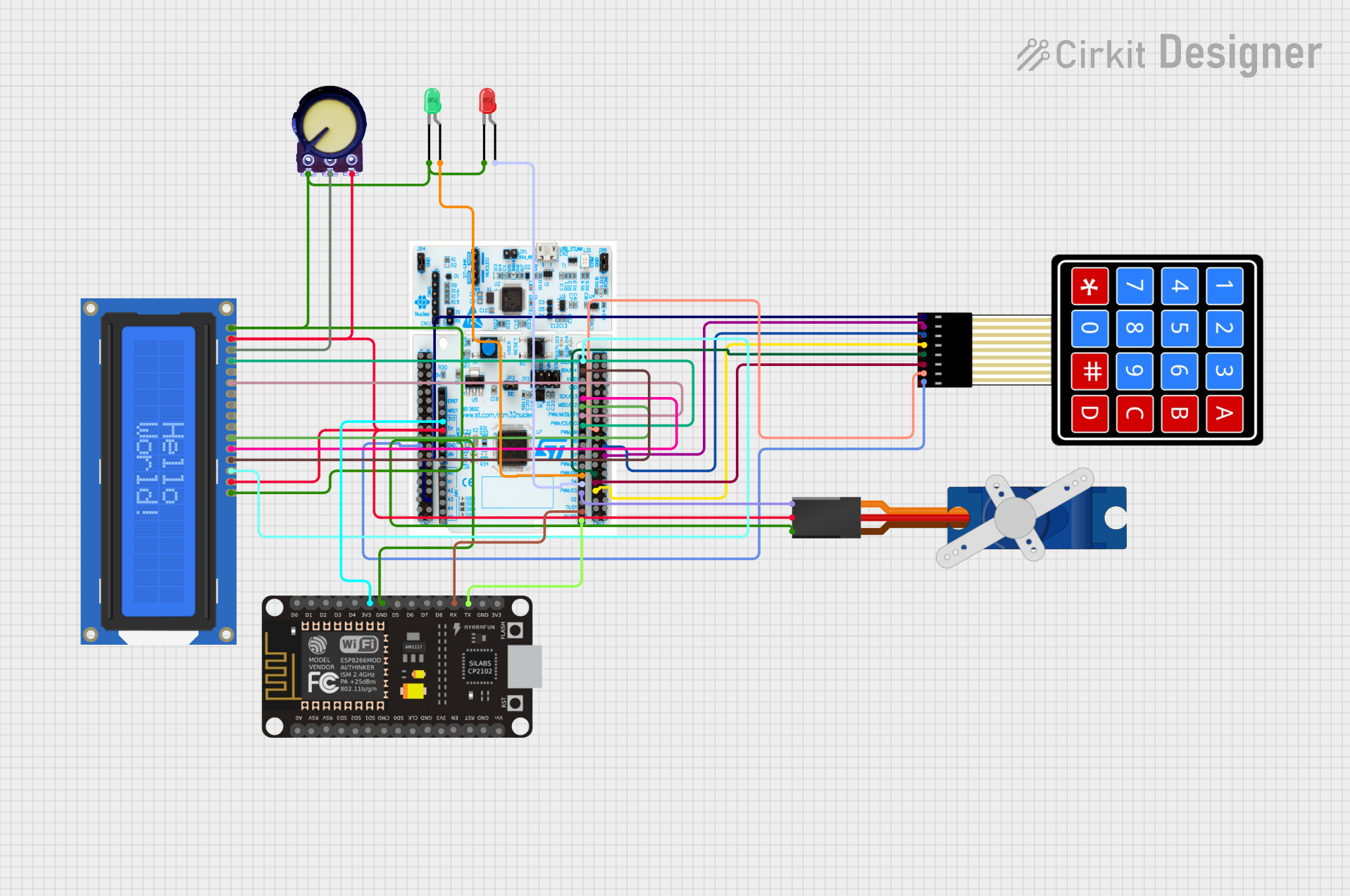
The circuit in question appears to be a security system that involves user interaction through a keypad and visual feedback via an LCD display. It includes a microcontroller (STM32 Nucleo 64 F411RE) for processing inputs and controlling outputs, an ESP8266 NodeMCU for WiFi connectivity, a 4x4 membrane matrix keypad for input, an Adafruit Standard LCD (16x2) for display, a potentiometer for contrast adjustment on the LCD, a Tower Pro SG90 servo motor for physical lock control, and two LEDs (green and red) for status indication.
Component List
Microcontrollers
- STM32 Nucleo 64 F411RE: A development board with an STM32 microcontroller, used for the main processing and control tasks in the circuit.
- ESP8266 NodeMCU: A WiFi module that enables remote communication and can be used for sending or receiving data over the internet.
Input Devices
- 4X4 Membrane Matrix Keypad: A 16-button keypad used for user input.
Output Devices
- Adafruit Standard LCD 16x2 white on blue: A 16-character by 2-line LCD display used for visual output.
- Tower Pro SG90 servo: A small servo motor used for actuating a physical lock mechanism.
- LED: Two Pin (green): A green LED used to indicate an unlocked state.
- LED: Two Pin (red): A red LED used to indicate a locked state.
Passive Components
- Potentiometer: A variable resistor used to adjust the contrast of the LCD display.
Wiring Details
STM32 Nucleo 64 F411RE
- LCD Connection: Digital pins D15, D14, D13, D12 are connected to the LCD's DB7, DB6, DB5, DB4 respectively. D11 is connected to the LCD's E pin, and D10 to the LCD's RS pin.
- LEDs: Digital pin D5 is connected to the anode of the green LED, and D4 to the anode of the red LED. Both LEDs share a common cathode connection to ground.
- Servo: Digital pin D3 is connected to the signal pin of the Tower Pro SG90 servo.
- ESP8266 NodeMCU Communication: Digital pins D1 and D0 are used for RX and TX communication with the ESP8266 NodeMCU.
- Keypad: The keypad's row and column connections are not explicitly defined in the net list.
ESP8266 NodeMCU
- Power: 3V3 pin is connected to the 3.3V output of the STM32 Nucleo board.
- Ground: GND pin is connected to the common ground.
- Communication: RX and TX pins are connected to the corresponding TX and RX pins of the STM32 Nucleo board.
Adafruit Standard LCD 16x2 white on blue
- Power: VDD pin is connected to the 5V output, and VSS pin to ground.
- Contrast: V0 pin is connected to the output of the potentiometer.
- Backlight: LED+ pin is connected to the 5V output, and LED- pin to ground.
Potentiometer
- Power: VCC pin is connected to the 5V output, and GND pin to ground.
- Output: The middle pin is connected to the V0 pin of the LCD for contrast control.
Tower Pro SG90 servo
- Power: +5V pin is connected to the 5V output, and GND pin to ground.
- Control: Signal pin is connected to digital pin D3 of the STM32 Nucleo board.
LEDs
- Green LED: Anode is connected to digital pin D5 of the STM32 Nucleo board, and cathode to ground.
- Red LED: Anode is connected to digital pin D4 of the STM32 Nucleo board, and cathode to ground.
Documented Code
STM32 Nucleo 64 F411RE Code
#include "stm32f4xx_hal.h"
#include <LiquidCrystal.h>
#include <Keypad.h>
#include <Servo.h>

LiquidCrystal lcd(D10, D11, D12, D13, D14, D15);
Servo servo;
String receivedOTP = "";
String enteredOTP = "";
bool locked = true;

// Keypad setup
const byte ROWS = 4;
const byte COLS = 4;
char keys[ROWS][COLS] = {
  {'1','2','3','A'},
  {'4','5','6','B'},
  {'7','8','9','C'},
  {'*','0','#','D'}
};
byte rowPins[ROWS] = {D7, D6, D5, D4};
byte colPins[COLS] = {D3, D2, D1, D0};
Keypad keypad = Keypad(makeKeymap(keys), rowPins, colPins, ROWS, COLS);

void setup() {
  lcd.begin(16, 2);
  servo.attach(D9);
  Serial.begin(9600);
  pinMode(D8, OUTPUT);  // Lock LED
  pinMode(D7, OUTPUT);  // Unlock LED
  lockDoor();
}

void loop() {
  if (Serial.available()) {
    receivedOTP = Serial.readStringUntil('\n');
  }

  char key = keypad.getKey();
  if (key) {
    if (key == '#') {
      checkOTP();
    } else {
      enteredOTP += key;
      lcd.setCursor(0, 1);
      lcd.print(enteredOTP);
    }
  }
}

void checkOTP() {
  if (enteredOTP == receivedOTP) {
    unlockDoor();
  } else {
    lcd.clear();
    lcd.setCursor(0, 0);
    lcd.print("Incorrect OTP");
    delay(2000);
    enteredOTP = "";
    lcd.clear();
  }
}

void lockDoor() {
  servo.write(0);  // Lock position
  locked = true;
  digitalWrite(D8, HIGH);  // Turn on Lock LED
  digitalWrite(D7, LOW);   // Turn off Unlock LED
  lcd.clear();
  lcd.setCursor(0, 0);
  lcd.print("Door Locked");
}

void unlockDoor() {
  servo.write(90);  // Unlock position
  locked = false;
  digitalWrite(D8, LOW);   // Turn off Lock LED
  digitalWrite(D7, HIGH);  // Turn on Unlock LED
  lcd.clear();
  lcd.setCursor(0, 0);
  lcd.print("Door Unlocked");
  delay(5000);  // Delay before auto-lock
  lockDoor();
}
ESP8266 NodeMCU Code
#include <ESP8266WiFi.h>
#include <BlynkSimpleEsp8266.h>

char auth[] = "your_BLYNK_AUTH_TOKEN";  // Replace with your Blynk Auth Token
const char* ssid = "your_SSID";         // Replace with your WiFi SSID
const char* password = "your_PASSWORD"; // Replace with your WiFi password

String otp = "1234";  // OTP to be sent to STM32

void setup() {
  Serial.begin(9600);
  WiFi.begin(ssid, password);

  while (WiFi.status() != WL_CONNECTED) {
    delay(1000);
  }

  Blynk.begin(auth, ssid, password);
}

void loop() {
  Blynk.run();
  if (/* Condition to send OTP */) {
    Serial.println(otp);
  }
}
(Note: The actual condition to send the OTP from the ESP8266 to the STM32 is not provided in the code snippet and should be implemented based on the specific requirements of the application.)