
ESP32-Based Ultrasonic Distance Measurement with Dual OLED Display
View and Edit Project In Cirkit Designer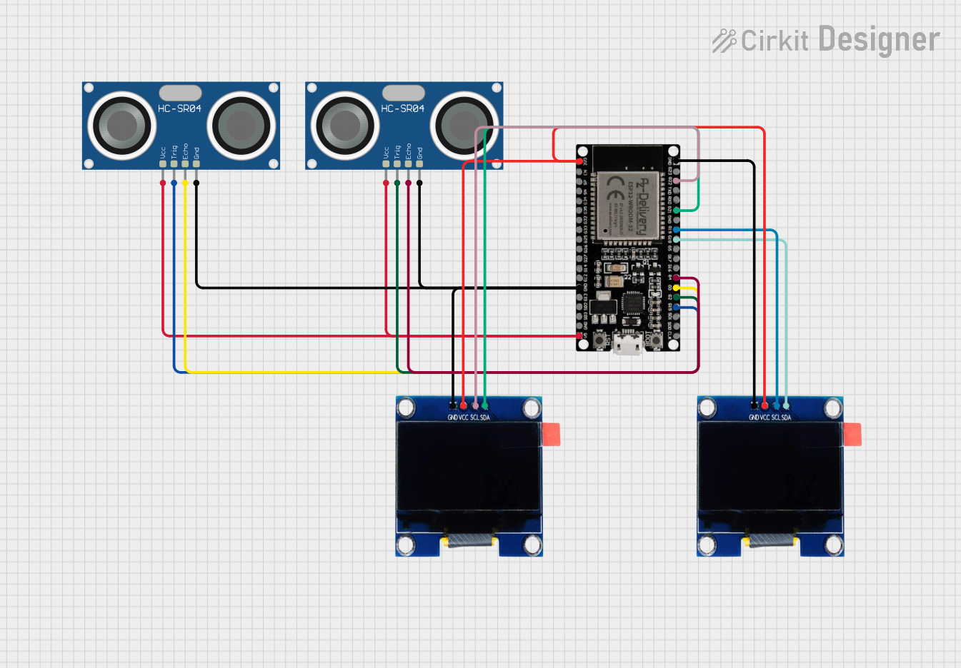
Circuit Documentation
Summary
The circuit in question is designed to interface an ESP32 microcontroller with two OLED displays and two HC-SR04 ultrasonic sensors. The ESP32 serves as the central processing unit, controlling the OLED displays for output and reading distance measurements from the ultrasonic sensors. The circuit is powered by the ESP32's 3.3V and 5V outputs, and communication with the OLED displays is achieved through I2C protocol, while the ultrasonic sensors are interfaced using GPIO pins.
Component List
ESP32 38 PINS
- Description: A microcontroller with Wi-Fi and Bluetooth capabilities, featuring a wide range of GPIO pins.
- Purpose: Acts as the central processing unit for controlling the OLED displays and reading data from the ultrasonic sensors.
OLED 1.3" Display
- Description: A small display with I2C interface, suitable for showing text and graphics.
- Purpose: To display distance measurements from the ultrasonic sensors.
HC-SR04 Ultrasonic Sensor
- Description: A sensor that measures distance by emitting ultrasonic waves and measuring the time taken for the echo to return.
- Purpose: To provide distance measurements to the ESP32 for display on the OLED screens.
Wiring Details
ESP32 38 PINS
- GND: Connected to the ground pins of both OLED displays and both HC-SR04 ultrasonic sensors.
- 3V3: Powers both OLED displays.
- 5V: Powers both HC-SR04 ultrasonic sensors.
- G22 (SCL_1): Connected to the SCL pin of the first OLED display.
- G21 (SDA_1): Connected to the SDA pin of the first OLED display.
- G19 (SCL_2): Connected to the SCL pin of the second OLED display.
- G18 (SDA_2): Connected to the SDA pin of the second OLED display.
- G4 (echoPin2): Reads the ECHO signal from the second HC-SR04 ultrasonic sensor.
- G0 (echoPin1): Reads the ECHO signal from the first HC-SR04 ultrasonic sensor.
- G2 (trigPin2): Sends the TRIG signal to the second HC-SR04 ultrasonic sensor.
- G15 (trigPin1): Sends the TRIG signal to the first HC-SR04 ultrasonic sensor.
OLED 1.3" Display (First Display)
- GND: Connected to the ground net.
- VCC: Powered by the 3V3 output from the ESP32.
- SCL: Connected to G22 (SCL_1) on the ESP32.
- SDA: Connected to G21 (SDA_1) on the ESP32.
OLED 1.3" Display (Second Display)
- GND: Connected to the ground net.
- VCC: Powered by the 3V3 output from the ESP32.
- SCL: Connected to G19 (SCL_2) on the ESP32.
- SDA: Connected to G18 (SDA_2) on the ESP32.
HC-SR04 Ultrasonic Sensor (First Sensor)
- VCC: Powered by the 5V output from the ESP32.
- TRIG: Connected to G15 (trigPin1) on the ESP32.
- ECHO: Connected to G0 (echoPin1) on the ESP32.
- GND: Connected to the ground net.
HC-SR04 Ultrasonic Sensor (Second Sensor)
- VCC: Powered by the 5V output from the ESP32.
- TRIG: Connected to G2 (trigPin2) on the ESP32.
- ECHO: Connected to G4 (echoPin2) on the ESP32.
- GND: Connected to the ground net.
Documented Code
/*
 * This Arduino Sketch is for an ESP32 microcontroller connected to two OLED
 * displays and two HC-SR04 ultrasonic sensors. The code initializes the
 * displays and sensors, reads distance measurements from the sensors, and
 * displays the readings on the respective OLED screens.
 */

#include <SPI.h>
#include <Wire.h>
#include <Adafruit_GFX.h>
#include <Adafruit_SSD1306.h>

#define SCREEN_WIDTH 128 // OLED display width, in pixels
#define SCREEN_HEIGHT 64 // OLED display height, in pixels

#define I2C_FREQ 400000
#define SDA_1 21
#define SCL_1 22
#define SDA_2 18
#define SCL_2 19
TwoWire I2C_1 = TwoWire(0);
TwoWire I2C_2 = TwoWire(1);

// Declaration for two SSD1306 displays connected to I2C (SDA, SCL pins)
Adafruit_SSD1306 display1(SCREEN_WIDTH, SCREEN_HEIGHT, &I2C_1);
Adafruit_SSD1306 display2(SCREEN_WIDTH, SCREEN_HEIGHT, &I2C_2);

// Pin definitions for ultrasonic sensors
const int trigPin1 = 15;
const int echoPin1 = 0;
const int trigPin2 = 2;
const int echoPin2 = 4;

void setup() {
  // Initialize serial communication
  Serial.begin(115200);

  I2C_1.begin(SDA_1, SCL_1);
  I2C_2.begin(SDA_2, SCL_2);

  // Initialize the OLED displays
  if(!display1.begin(SSD1306_SWITCHCAPVCC, 0x3C)) {
    Serial.println(F("SSD1306 allocation failed for display1"));
    for(;;);
  }
  if(!display2.begin(SSD1306_SWITCHCAPVCC, 0x3C)) {
    Serial.println(F("SSD1306 allocation failed for display2"));
    for(;;);
  }

  display1.display();
  display2.display();
  delay(1000);

  // Clear the buffer.
  display1.clearDisplay();
  display1.display();
  display2.clearDisplay();
  display2.display();

  // text display tests

  display1.setTextSize(1);
  display1.setTextColor(SSD1306_WHITE);
  display1.setCursor(0, 0);
  display1.print("This is some text");
  display1.print("it works!");
  display1.println("more text here");
  display1.println("and even more");
  display1.setCursor(0, 0);
  display1.display();  // actually display all of the above

  // text display tests
  // OLED2.invertDisplay(true);
  display2.setTextSize(2);
  display2.setTextColor(SSD1306_WHITE);
  display2.setCursor(0, 0);
  display2.println("This is");
  display2.println("OLED 2");
  display2.setCursor(0, 0);
  display2.display();  // actually display all of the above
  delay(2000);

  display1.clearDisplay();
  display1.display();
  display2.clearDisplay();
  display2.display();

  // Initialize the ultrasonic sensor pins
  pinMode(trigPin1, OUTPUT);
  pinMode(echoPin1, INPUT);
  pinMode(trigPin2, OUTPUT);
  pinMode(echoPin2, INPUT);
}

void loop() {
  // Read distance from the first ultrasonic sensor
  long duration1, distance1;
  digitalWrite(trigPin1, LOW);
  delayMicroseconds(2);
  digitalWrite(trigPin1, HIGH);
  delayMicroseconds(10);
  digitalWrite(trigPin1, LOW);
  duration1 = pulseIn(echoPin1, HIGH);
  distance1 = duration1 * 0.034 / 2;

  // Read distance from the second ultrasonic sensor
  long duration2, distance2;
  digitalWrite(trigPin2, LOW);
  delayMicroseconds(2);
  digitalWrite(trigPin2, HIGH);
  delayMicroseconds(10);
  digitalWrite(trigPin2, LOW);
  duration2 = pulseIn(echoPin2, HIGH);
  distance2 = duration2 * 0.034 / 2;

  // Display the distance on the first OLED display
  display1.clearDisplay();
  display1.setTextSize(1);
  display1.setTextColor(SSD1306_WHITE);
  display1.setCursor(0, 0);
  display1.print(F("Distance 1: "));
  display1.print(distance1);
  display1.print(F(" cm"));
  display1.display();

  // Display the distance on the second OLED display
  display2.clearDisplay();
  display2.setTextSize(1);
  display2.setTextColor(SSD1306_WHITE);
  display2.setCursor(0, 0);
  display2.print(F("Distance 2: "));
  display2.print(distance2);
  display2.print(F(" cm"));
  display2.display();

  // Wait for a short period before taking the next measurement
  delay(500);
}
Note: The code provided is for an Arduino sketch that initializes the components, reads sensor data, and displays the information on the OLED screens. The pin definitions in the code correspond to the wiring details provided in the previous section.