
Battery-Powered Peltier Module and Fan Cooling System with LED Indicator
View and Edit Project In Cirkit Designer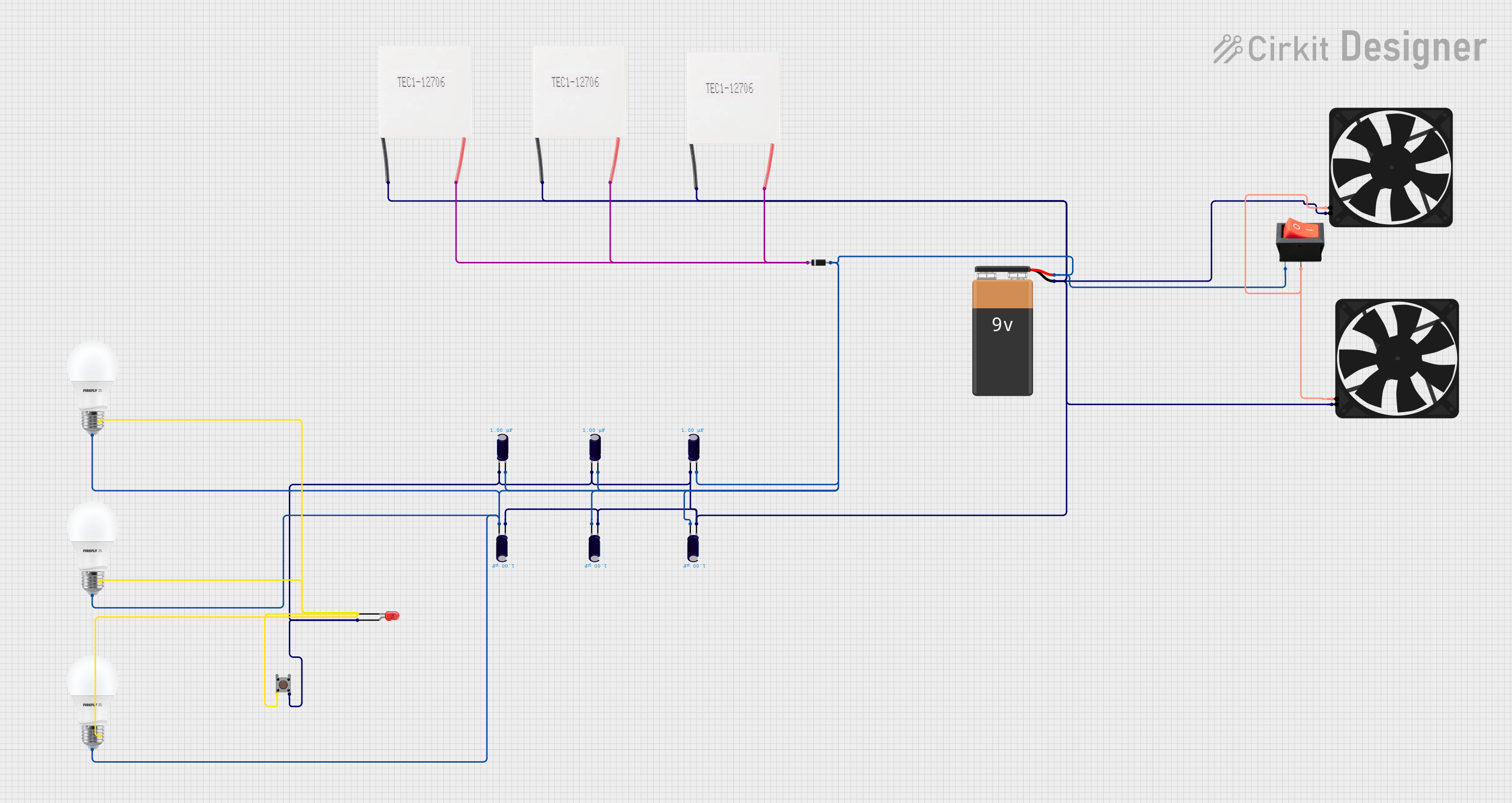
Circuit Documentation
Summary
This circuit consists of multiple Peltier modules, LEDs, fans, capacitors, a diode, a battery, bulbs, a rocker switch, and a pushbutton. The circuit is designed to manage power distribution and control various components using a rocker switch and a pushbutton. The Peltier modules are used for thermal management, while the fans provide cooling. The LEDs and bulbs serve as indicators, and the capacitors are used for filtering and energy storage.
Component List
Peltier Module
- Pins: Negative, Positive
- Description: Used for thermal management.
- Purpose in Circuit: Provides heating or cooling based on the direction of current flow.
LED: Two Pin (red)
- Pins: Cathode, Anode
- Description: Red LED.
- Purpose in Circuit: Serves as an indicator.
9V Battery
- Pins: -, +
- Description: Power source.
- Purpose in Circuit: Provides power to the circuit.
Diode
- Pins: Cathode, Anode
- Description: Standard diode.
- Purpose in Circuit: Ensures current flows in one direction.
Fan
- Pins: GND, 5V
- Description: Cooling fan.
- Purpose in Circuit: Provides cooling.
BULB
- Pins: +, -
- Description: Standard bulb.
- Purpose in Circuit: Serves as an indicator.
Electrolytic Capacitor
- Pins: -, +
- Description: Capacitor with 0.000001 Farads capacitance.
- Purpose in Circuit: Used for filtering and energy storage.
Rocker Switch
- Pins: Output, Input
- Description: Standard rocker switch.
- Purpose in Circuit: Controls the power to the circuit.
Pushbutton
- Pins: Pin 3 (out), Pin 4 (out), Pin 1 (in), Pin 2 (in)
- Description: Standard pushbutton.
- Purpose in Circuit: Provides user input to the circuit.
Wiring Details
Peltier Module
Negative Pin:
- Connected to the negative pin of the 9V Battery.
- Connected to the negative pins of all Electrolytic Capacitors.
- Connected to the GND pins of both Fans.
- Connected to the anode pin of the LED.
- Connected to Pin 4 (out) of the Pushbutton.
Positive Pin:
- Connected to the cathode pin of the Diode.
- Connected to the positive pins of other Peltier Modules.
LED: Two Pin (red)
Cathode Pin:
- Connected to the negative pins of all Bulbs.
- Connected to Pin 2 (in) of the Pushbutton.
Anode Pin:
- Connected to the negative pin of the 9V Battery.
- Connected to the negative pins of all Electrolytic Capacitors.
- Connected to the GND pins of both Fans.
- Connected to the negative pins of all Peltier Modules.
- Connected to Pin 4 (out) of the Pushbutton.
9V Battery
- Pin:
- Connected to the negative pins of all Electrolytic Capacitors.
- Connected to the GND pins of both Fans.
- Connected to the anode pin of the LED.
- Connected to the negative pins of all Peltier Modules.
- Connected to Pin 4 (out) of the Pushbutton.
+ Pin:
- Connected to the input pin of the Rocker Switch.
- Connected to the positive pins of all Electrolytic Capacitors.
- Connected to the positive pins of all Bulbs.
- Connected to the anode pin of the Diode.
Diode
Cathode Pin:
- Connected to the positive pins of all Peltier Modules.
Anode Pin:
- Connected to the input pin of the Rocker Switch.
- Connected to the positive pins of all Electrolytic Capacitors.
- Connected to the positive pins of all Bulbs.
- Connected to the positive pin of the 9V Battery.
Fan
GND Pin:
- Connected to the negative pin of the 9V Battery.
- Connected to the negative pins of all Electrolytic Capacitors.
- Connected to the anode pin of the LED.
- Connected to the negative pins of all Peltier Modules.
- Connected to Pin 4 (out) of the Pushbutton.
5V Pin:
- Connected to the output pin of the Rocker Switch.
BULB
- Pin:
- Connected to the cathode pin of the LED.
- Connected to Pin 2 (in) of the Pushbutton.
+ Pin:
- Connected to the input pin of the Rocker Switch.
- Connected to the positive pins of all Electrolytic Capacitors.
- Connected to the anode pin of the Diode.
- Connected to the positive pin of the 9V Battery.
Electrolytic Capacitor
- Pin:
- Connected to the negative pin of the 9V Battery.
- Connected to the GND pins of both Fans.
- Connected to the anode pin of the LED.
- Connected to the negative pins of all Peltier Modules.
- Connected to Pin 4 (out) of the Pushbutton.
+ Pin:
- Connected to the input pin of the Rocker Switch.
- Connected to the positive pins of all Bulbs.
- Connected to the anode pin of the Diode.
- Connected to the positive pin of the 9V Battery.
Rocker Switch
Input Pin:
- Connected to the positive pin of the 9V Battery.
- Connected to the positive pins of all Electrolytic Capacitors.
- Connected to the positive pins of all Bulbs.
- Connected to the anode pin of the Diode.
Output Pin:
- Connected to the 5V pins of both Fans.
Pushbutton
Pin 1 (in):
- Not connected.
Pin 2 (in):
- Connected to the cathode pin of the LED.
- Connected to the negative pins of all Bulbs.
Pin 3 (out):
- Not connected.
Pin 4 (out):
- Connected to the negative pin of the 9V Battery.
- Connected to the negative pins of all Electrolytic Capacitors.
- Connected to the GND pins of both Fans.
- Connected to the anode pin of the LED.
- Connected to the negative pins of all Peltier Modules.
Code
No microcontroller code is provided for this circuit.