
ESP32-Based Object Detection and Distance Measurement System with I2C LCD Feedback
View and Edit Project In Cirkit Designer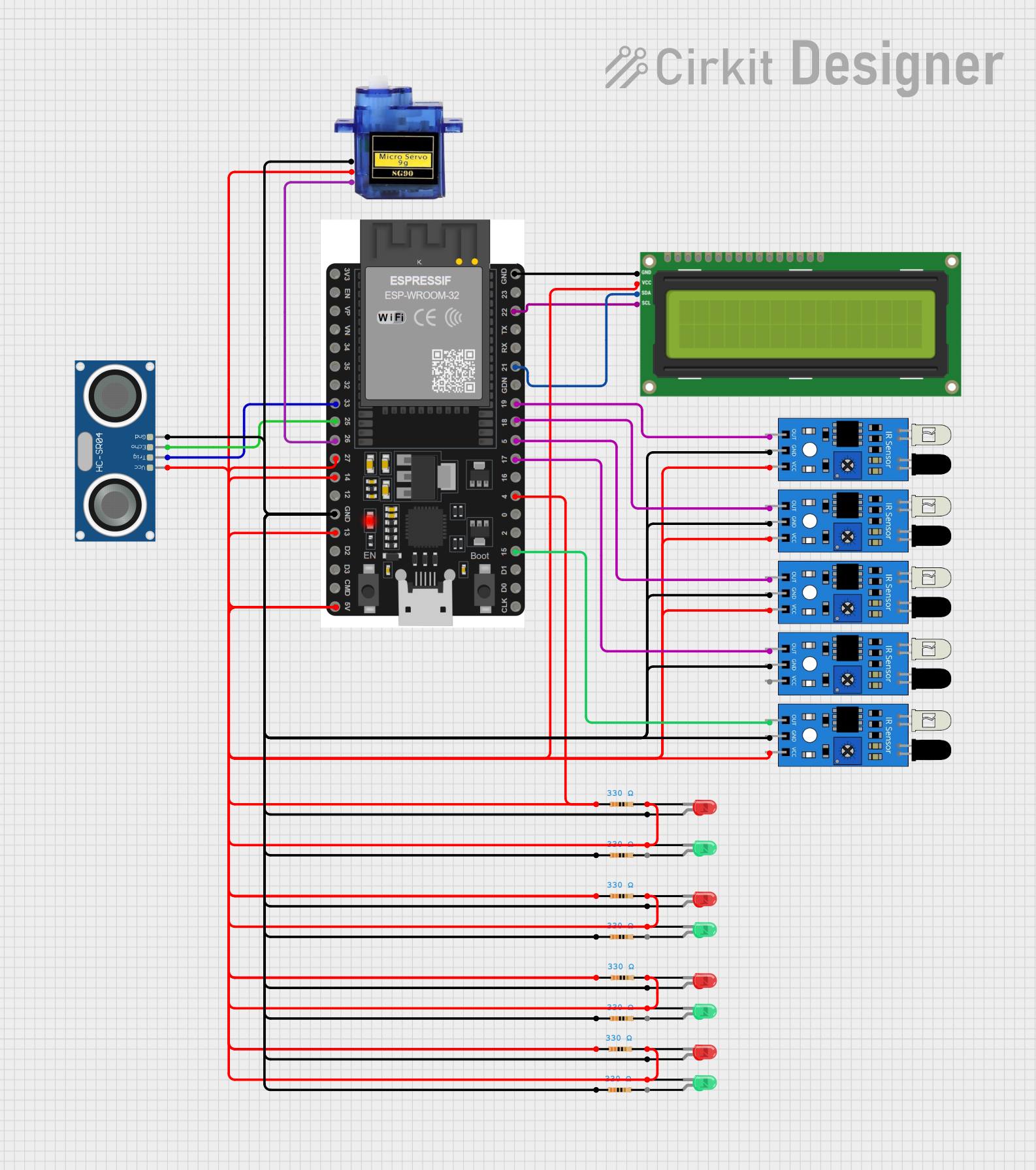
Circuit Documentation
Summary
The circuit in question is designed to interface an ESP32 microcontroller with a variety of sensors and output devices. The ESP32 is connected to an I2C LCD screen, multiple IR sensors, an HC-SR04 ultrasonic sensor, a micro servo, and several LEDs with current-limiting resistors. The IR sensors and the ultrasonic sensor are likely used for distance or motion detection, while the servo and LEDs may indicate status or respond to sensor inputs. The LCD screen can display data or status messages.
Component List
ESP32 38 PINS
- Microcontroller with WiFi and Bluetooth capabilities.
- It has a variety of GPIO pins for interfacing with other components.
I2C LCD 16x2 Screen
- A 16x2 character LCD display that uses the I2C communication protocol.
IR Sensor
- An infrared sensor used for detecting proximity or measuring distance.
HC-SR04 Ultrasonic Sensor
- An ultrasonic ranging module that provides 2cm to 400cm non-contact measurement functionality.
Micro Servo 9G
- A small servo motor capable of precise angular movement.
LED: Two Pin (Red/Green)
- Light Emitting Diodes used as visual indicators.
Resistor
- A passive component used to limit current, typically to protect LEDs.
Wiring Details
ESP32 38 PINS
- GND connected to the GND of all components.
- 22/SCL connected to SCL of I2C LCD Screen.
- 21/SDA connected to SDA of I2C LCD Screen.
- 19, 18, 5, 17/TX2, 15 connected to the output of different IR sensors.
- 33 connected to TRIG of HC-SR04 Ultrasonic Sensor.
- 25 connected to ECHO of HC-SR04 Ultrasonic Sensor.
- 26 connected to PWM of Micro Servo 9G.
- 4, 27, 14, 13, 5V/VIN connected to various components for power and control signals.
I2C LCD 16x2 Screen
- SCL connected to 22/SCL of ESP32.
- SDA connected to 21/SDA of ESP32.
- VCC (5V) and GND connected to 5V and GND of ESP32 respectively.
IR Sensor
- out connected to various GPIO pins on the ESP32 for signal output.
- gnd connected to GND of ESP32.
- vcc connected to 5V/VIN of ESP32.
HC-SR04 Ultrasonic Sensor
- TRIG connected to GPIO 33 of ESP32.
- ECHO connected to GPIO 25 of ESP32.
- VCC connected to 5V/VIN of ESP32.
- GND connected to GND of ESP32.
Micro Servo 9G
- PWM connected to GPIO 26 of ESP32.
- +5V connected to 5V/VIN of ESP32.
- GND connected to GND of ESP32.
LED: Two Pin (Red/Green)
- anode connected to various GPIO pins on the ESP32 through current-limiting resistors.
- cathode connected to GND of ESP32.
Resistor
- Connected in series with LEDs to limit the current through them.
Documented Code
No code was provided for the microcontrollers in the circuit. Typically, the code would be used to control the behavior of the microcontroller, read sensor inputs, drive the servo, update the LCD display, and control the state of the LEDs. Without the code, the specific functionality and interaction between the components cannot be documented.